A Smart Hardware component is essentially an Autodesk Inventor component equipped with iLogic rules that implement the behavioural logic of this component. This can be in the form of logic for the placement intervals, orientation, configuration and other logic of the component. Each time such a component is placed in a furniture structure with the Hardware Attach command, the component is copied, placed in space and its iLogic rules are executed, which determine its behaviour in the connection.
Let us introduce a few concepts that are necessary for further explanation.
Connection Patch and Connection Coordinate System
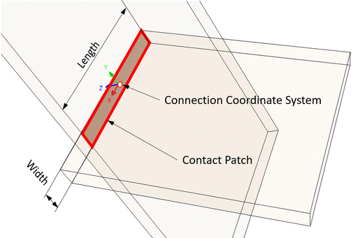
The user selects the panels to be connected. The panels to be connected come into contact with each other and form a Contact Patch. Woodwork for Inventor is able to automatically find such a patch for the specified plates if they are touching each other or are adjacent to each other within a specified gap. The actual contact patch may not be rectangular. Woodwork for Inventor always calculates the shape of the patch as a Surrounding rectangle. It also calculates the length and width of this patch and finds the Connection Coordinate System, which is always at the center of the patch.
In addition to the length and width, Woodwork for Inventor calculates other connection characteristics that can be passed as parameters to the Smart Hardware component at the time it is applied to the furniture structure. These parameters can be accessed and interpreted by a user-created iLogic rule in the Smart Hardware component and the configuration of the Smart Hardware component can be adapted accordingly.
Also, during the Hardware Attachment command, the component is placed so that its Origin Coordinate System is matched to the Connection Coordinate System. It is important for the user designing a Smart Hardware component to have an idea of how the component is to be aligned with respect to the contact patch and how the transmitted connection parameters are to influence the component configuration. The connection parameters that can be found by Woodwork for Inventor are described below. The binding of the found parameters to the parameters generated by the Smart Hardware is done during the component registration.
Two cases are provided for the placement of Smart Hardware in a furniture structure:
Woodwork for Inventor can provide the following parameters about the connection location:
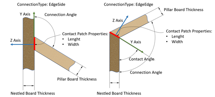
 Orientation of the Connection Coordinate System depending on the direction specified for the EdgeSide connection
 Orientation of the Connection Coordinate System depending on the direction specified for the EdgeEdge connection
|
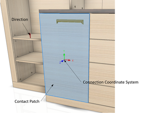
Let’s say we have a furniture door and we need to place a door knob on the door. The user selects the surface of the door on which the handle is to be placed. In this case, the Contact Patch of the Smart Hardware component is the entire surface of the door. The designer of the Smart Hardware component has to design the component so that it is positioned correctly in relation to the specified surface.
Such a connection may provide the following data about itself:
The Contact Patch is created as the surrounding rectangle of minimum area. If the specified flat face is rectangular, then the Contact Patch will match the shape of the face. The Connection Coordinate System is always located at the center of the calculated rectangle and the Z axis is always coincident with the normal of the specified face. The X axis of the Coordinate System is aligned with either side of the calculated rectangle. For the purpose of making the decision, a direction vector is specified, from which the Y axis of the Coordinate System is determined. If no direction vector is specified, then the normal vector of the View Cube Top plane is taken by default.
 The orientation of the contact patch Coordinate System depending on the specified direction
The example shows how the specification of a direction vector affects the orientation of the Connection Coordinate System. At the same time, it influences the orientation of the Smart Hardware component.
|