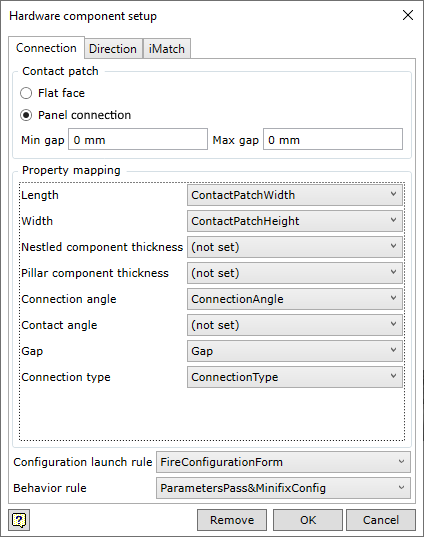
Contact patch
|
|
|
|
Flat Face
|
Defines that the Smart Hardware component will be placed on the specified flat face of the part. These are usually components that do not connect, but perform a certain function on the part. For example, knob, feet, etc.
|
|
Panel Connection
|
Defines the connection between two panels by a Smart Hardware component.
|
|
Min gap; Max gap
|
It is possible to set the gap range, in which the connection of the panels is sought. The panels to be joined may or may not be in direct contact with each other. An example of a component requiring a gap may be a door hinge, shelf bracket, etc.
|
Property Maping
|
In this section, the user sees which connection parameters are generated during the connection analysis. The designer of the Smart Hardware component can bind these parameters to any parameter he/she has created in the component he/she is developing. What these parameters mean can be found in this section.
|
|
Length
|
The length of the contact patch.
|
|
Width
|
The width of the contact patch.
|
|
Nestled board thickness
|
Thickness of the nestled board.
|
|
Pillar board thickness
|
Thickness of the pillar board.
|
|
Connection angle
|
Angle between the connecting panels.
|
|
Contact angle
|
Angle between the contact patch and the nestled board. Relevant for EdgeEdge connections.
|
|
Gap
|
The actual gap between the panels to be connected.
|
|
Connection type
|
Connection type: This parameter can take two textual values: EdgeSide and EdgeEdge.
|
Configuration launch rule
|
If the designed Smart Hardware component includes the possibility to configure it additionally, a rule has to be created to launch the configuration form and this rule has to be specified when registering the component. This will influence whether the component can be reconfigured or not.
|
Behavior rule
|
If the behavioural logic of the Smart Hardware is implemented by some user-created iLogic rule, it is necessary to specify this rule when registering the component.
|