Labels & Sheet templates - this tab is used to set what symbols will represent different label types and specify what sheet template will be used for a component drawing.
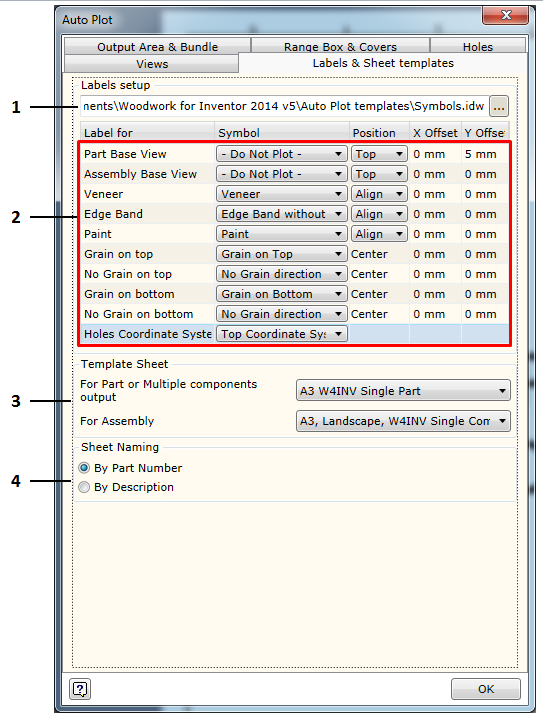
1. Selecting a (*.idw) file containing symbols required to represent label information. For Woodwork for Inventor, such symbol file is located at C:\Users\Public\Documents\Woodwork for Inventor 2014 v5\Auto Plot templates\Symbols.idw. The user may indicate a different file where symbol created by him are stored.
2. Area in which all possible label options are provided supporting the visualization of Woodwork for Inventor information in the drawing. Currently, the following labels of this type are available:
a. Assembly Base View - label for the export of the main assembly parameters: assembly code and assembly name. The label is only exported for the base view. b. Part Base View - label for the export of the main part parameters: part code and part name, fill material name, dimensions, etc. c. Veneer - label for the export of information about veneer or film material. d. Edge Band - label for the export of information about edge band material. e. Paint – label for the export of information about paint coating. f. Grain on Top - a symbol representing the fill grain direction where the main face of the part is pointed toward the observer. It is important in setting the right, left, front and back sides of the part. Click here for more information. g. Grain on bottom - a symbol representing the fill grain direction where the main face of the part is pointed away from the observer. h. No Grain on Top - a symbol representing a direction based on which the blank size of the part is calculated if the main face of the part is pointed toward the observer. i. No Grain on Bottom - a symbol representing a direction based on which the blank size of the part is calculated if the main face of the part is pointed away from the observer. j. Holes Coordinate System - a symbol representing the starting point of the holes coordinate system based on which the coordinates of all holes to be placed in the holes table are calculated. |
3. Area in which the user can select which sheet formats in the template file will be used when creating a component drawing. Here two possible options can be selected:
a. For Part or Multiple components output - selecting a format for part or multiple component output in a single sheet. b. For Assembly - selecting a sheet format for assembly component output. |
4. Area in which the user can set the field by which the name of the output sheet/file will be created. Options available:
a. By Part Number - when creating a name, a component iProperty field Part Number is used as a basis. b. By Description - when creating a name, a component iProperty field Description is used as a basis. If the name is used repeatedly (e. g. the name “Side”), additional number index is given to the repeated name. |
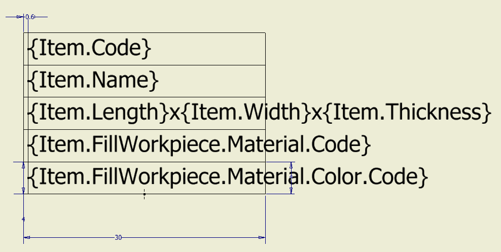
As previously mentioned, each label type is associated with a drawing symbol selected from the symbol file. Symbols are created following the Autodesk Inventor rules. Also, Prompted Entry fields can be included in some label symbols. If the value of the field being included corresponds to the keyword of the Woodwork for Inventor BOM generator, the Auto Plot command, during the symbol insertion process, will interpret this field and take relevant data from the Woodwork for Inventor data stored in the part. Then this data will be placed to a relevant symbol field contained in the drawing. The use of Prompted Entry fields during symbol insertion. Using Prompted Entry fields, each label type can provide information about relevant Woodwork for Inventor data. The example below shows the symbol definition of the Part Base View label in the Symbols.idw file:
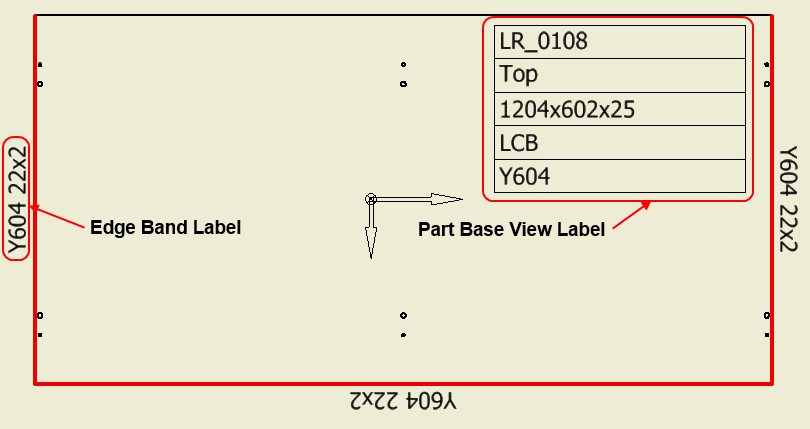
Such symbol automatically placed in the drawing will look like this:
As you can see, the field values are read from the part data and placed in relevant symbol fields. On the left of the figure, an analogous Edge Band label symbol is circled which contains a material color field.
|
As you may notice, the Prompted Entry fields in symbols are named similarly as in BOM templates. Depending on the label type, default fields may be used in symbols. Tables below show what fields can be used in symbols defining relevant label type. Assembly Base View Label - label of the assembly base view projection
Part Base View Label - label of the part base view projection.
Veneer, Edge Band, Paint - cover labels.
Title Block - filling up fields of the title block. Just like Prompted Entry fields can be included in a symbol, the same fields can be used in the Title Block description. For the title block, the same fields can be used as in the case of Assembly Base View and Part Base View labels.
|
Each Autodesk Inventor symbol has its own base point called Connection Point Grip. It is with respect to this point that symbol positioning in the drawing is defined. The definition of this position depends on the label type. We will look into possible positioning descriptions for each uniformly described label group.
Base view labels.
These labels include: ▪Assembly Base View ▪Part Base View
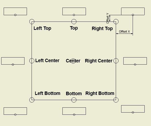
These labels are positioned in the drawing for the base view and it is performed with respect to the defined output area. If a request was made to place several view projections for the same component, the base area will scaled to fit due to the division of the output area into sub-areas for multiple view output. In this case label positioning is performed with respect to the sub-area of the base view. The labels of this type can have a pre-defined position.
As you can see in the figure, you may additionally define symbol repositioning values (along X and Y directions) which are calculated based on the specified base point.
Cover marking labels.
These labels include: ▪Veneer ▪Edge Band ▪Paint
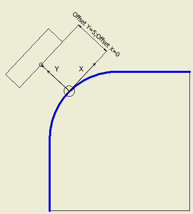
The initial positioning point for these labels is found based on the cover reflecting the centerpoint of the curve.
Symbol repositionings are performed with respect to this point, if such were specified by the user.
The Position option allows the user to specify label symbol alignment: ▪Align - label symbol which is aligned tangentially to the curve at the positioning point. ▪Not rotate - symbol which is placed horizontally.
Grain direction labels. These labels include: ▪Grain on Top ▪Grain on bottom ▪No Grain on Top. ▪No Grain on Bottom
These labels are placed in the centerpoint of the view projection. The user may specify the repositioning values for these labels from the center to X and Y directions.
|