Output area & Bundle - this tab is used to define the space intended for view output in the sheet and to select the type of drawing bundle as well as to include component types into documentation.
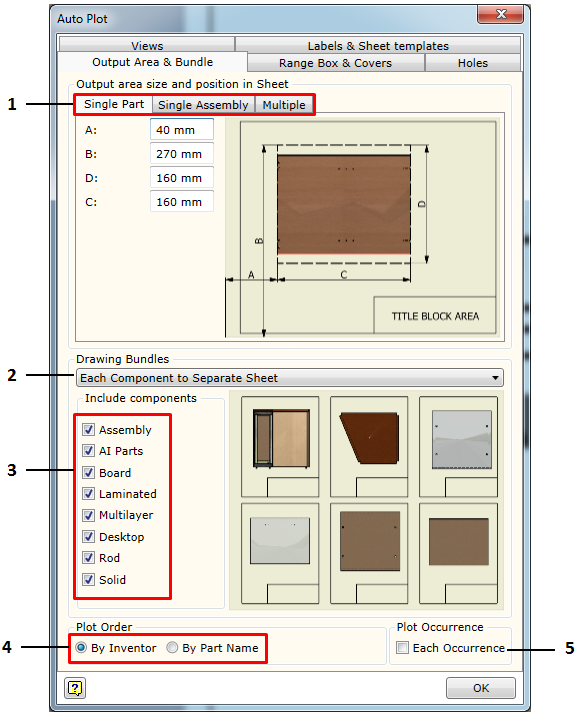
1. Tabs intended to define spaces for component view output:
a. Part - defines the output area for a single part in the sheet. One should bear in mind that if the Auto scale is selected, all views requested for a given component type will be fitted in this area. In this case, it is a Part type component. During the view output process, the Woodwork for Inventor, taking into account the configuration of the requested view projections, automatically divides the requested area into equal parts and fits them in relevant sub-areas. If a specific scale for the output views has been requested, this area division will not be applicable. In this case, only the start point of the left upper corner of the view projection will be taken into consideration. b. Assembly – defines the output area for a single assembly. In this case, the same placement rules apply as in the case of the part. c. Multiple Components - defines multiple component placement in a single sheet. |
2. Selecting what bundle the user wants to form on the basis of the template being created. The composition of the bundle is illustrated by the option selection dialog box below. The yellow sheet in the white background symbolizes a separate file. The yellow background with a frame in it symbolizes a separate sheet in a file. The following are default bundle options:
|
a. Each Component to separate File. The add-on scans the selected assembly file and places each component (a component is considered to be an assembly or a part) into a separate drawing file. This method is applicable when working with Autodesk Vault software and each component has a model file and a drawing file corresponding this file. b. Each Component to separate Sheet. The drawings of all components are placed in a single file but at the same time a separate sheet is created for each component within a file. c. Each component to Same Sheet. All components are placed in a single file, and, based on the multiple component placement scheme, attempts are made to fit all components into a single sheet. This scheme is defined by setting an output area. If all components do not fit in a single sheet, another sheet is automatically created in which the remaining components are placed. The process continues until all required components are placed in the sheets. d. Parent component to separate file Children to separate Sheet. The parent component (usually an assembly) is plotted to a separate file. All “children” of this assembly (these may include parts or other sub-assemblies) are plotted to a separate file, in which each of them are placed in a separate sheet. e. Parent component to separate file Children to same Sheet. The parent component is plotted to a separate file. All children of this assembly are plotted to a separate file in which, based on the multiple component placement scheme, each of them is placed in the same sheet. f. Parent component to Same file Children to same Sheet. The parent component and its “children” are placed in the same file. However, a separate sheet is given to the parent component, whereas its children are placed based on the multiple component placement scheme. |
3. Setting components to be included in documentation. The user can select which components need to be included in the drawing bundle and which must be ignored.
4. Setting order for plotting. This option is important when performing drawing placement in a single file.
|
a. By Inventor - plotting is performed in the same order in which components are read moving across the internal assembly structure. b. By Part Name - plotting is performed in the alphabetical order, sorting components by Part Name field value. |
5. Each Occurrence - the drawing is reapplied to each component occurrence in the auto plotted assembly.