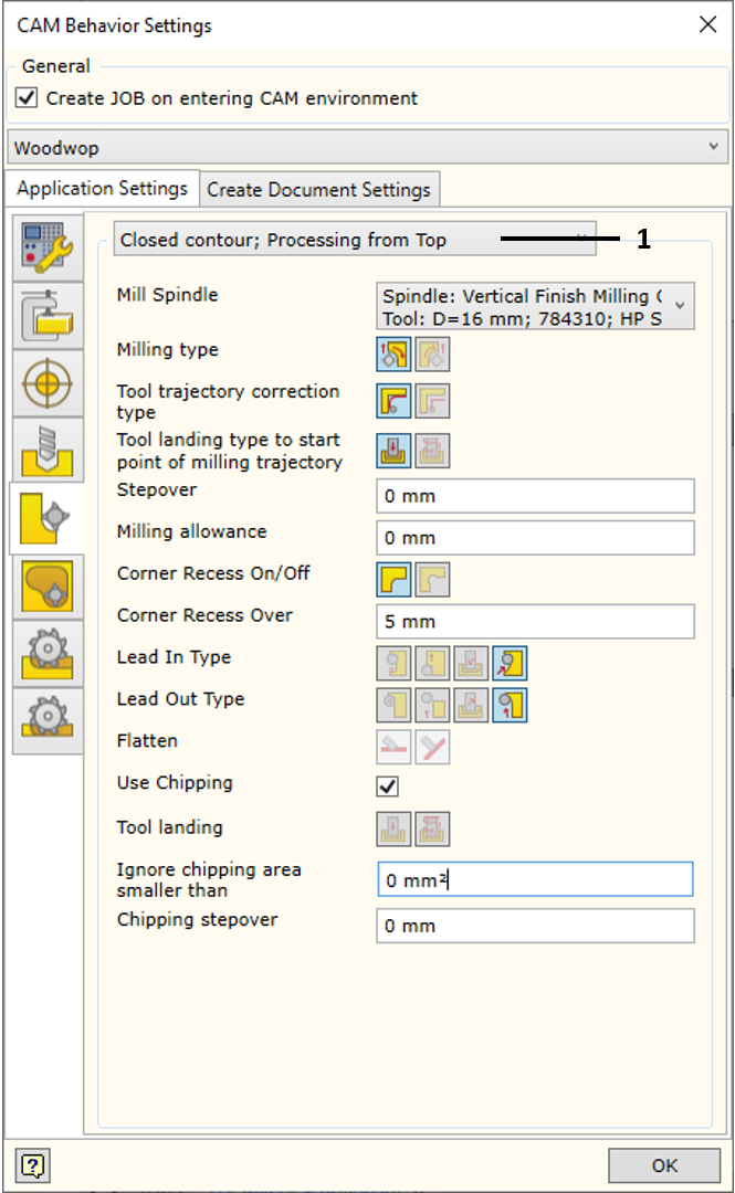
Milling operation has parameters controlling various aspects of the technology being created, such as: the side, from which the loop is followed, ways of cutting into the loop, etc. The technology is created for all spindles included in the configuration of the machine, thus milling operation settings may differ for the processing using top oriented, side oriented or free oriented spindle. Milling operation settings can also differ for open and closed contours. Therefore, the software allows the user to adjust these aspects separately for top oriented, side oriented and free oriented spindle, while taking into account whether this is closed or open milling contour.
These settings are accessed from the milling operation settings tab.

1. Orientation and Loop Type Selector |
Selektorius leidžia pasirinkti, kokiai špindelio orientacijai ir kokio tipo kontūrui bus taikomi žemiau užrašyti nustatymai. Galimos šios situacijos:
▪Closed Contour. Top oriented spindle - settings for closed contours, which require processing from the top.
▪Closed Contour. Side oriented spindle - settings for closed contours, which require processing from the side.
▪Closed Contour. Free oriented spindle - settings for closed contours, which require processing using free oriented spindle.
▪Open Contour. Top oriented spindle - settings for open contours, which require processing from the top.
▪Open Contour. Side oriented spindle - settings for open contours, which require processing from the side.
▪Open Contour. Free oriented spindle - settings for open contours, which require processing using free oriented spindle.
Different spindles and different operation parameters can be specified for individual situations.
|
Mill Spindle or Milling Style |
For the spindle orientation set in the selector, the machine spindle or the milling style is selected. The parameters of the operation to be created by the CAM solver are then set for this spindle. In case a milling style is selected, all processing settings come from the saved style settings. Currently, the style can only be selected for vertical processing.
|
Milling type |
Setting the side, from which the loop is followed, and the milling type. To read more, click here.
|
Tool Trajectory correction type |
Setting the correction type. To read more, click here. Keep in mind that in cases, where the calculation method of machine trajectory is given as the original contour, it is impossible to ask the program to generate repositioned contour.
|
Tool landing type to start point of milling trajectory |
Landing type to the start point of contour milling trajectory. To read more, click here.
|
Milling allowance |
Milling allowance.
|
Corner Recess On/Of |
Additional corner recess. To read more, click here.
|
Corner Recess Over |
Setting the size of the corner recess.
|
Lead In Type |
Setting the trajectory of lead in: cutting into the milling contour.
|
Lead Out Type |
Setting the trajectory of lead out: pulling away from the milling contour cut.
|
Flatten |
If Free Oriented milling is defined, it is possible to define how the tool trajectories are calculated. They can be slanted or flattened. More information is available here. |
Use Chipping |
The remnant chipping option is activated during the automatic generation of the Mill operation. The remnant areas are automatically identified and processed during the milling operation. |
Tool landing
|
Determines how deep the tool has to go into the material before it can start the milling contour loop. |
Chipping stepover |
Sets the height of the remnant chipping pass. |