What is Rest Milling?
When milling a contour, there are times when it is not rational to process the contour with one tool. Choosing a tool with a large diameter allows you to quickly go around the contour, but leaves pieces of material unremoved. Taking a thin tool means using modes that preserve the tool. This can be multiple contour milling, approaching the material with a fine step, or appropriate slow cutting modes. In this case, a combination of a large and a small tool works best. This type of processing, where several milling tools are combined (the first tool removes the main material and the next tool mills out the residue), is called Rest Milling.
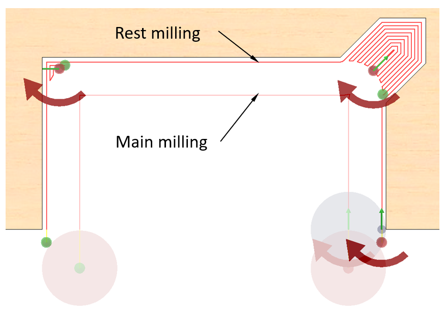
Rest milling explanation
What is an Edge Cut?
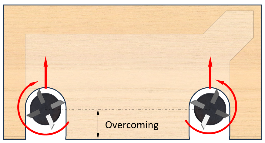
If the processed part is covered with edge banding, then there is a risk that the Mill may tear the edge banding during entry or exit depending on the direction of rotation. To avoid this, a combination of two tools rotating in different directions can be used. The tools are operated in such a way that they approach the contour so that the milling cutter blade presses the edge banding against the part during rotation, as shown in the figure below. It is enough to make an approach on one side and another on the other, and then any tool can be run through the cuts without the risk of tearing the edge banding.
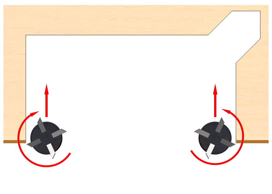
Banded edge milling
All of the above operations use the same contour geometry. It is therefore appropriate to combine them into a single operation on the same contour. This description of the tools of the joint operation is called a style. In the contour milling command, this style can be created, saved and then reapplied in contour processing operations. Styles are saved in the Woodwork for Inventor database.
See below for a description of how to do this.
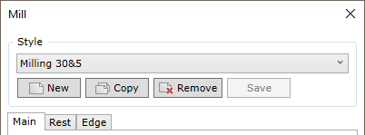
The following operations can be performed on a style:
Style
|
Allows you to select a style from a list of previously created styles and make it active. The list includes the option “No Mill Style”. In this case, the milling command works only with the main tool.
|
New
|
Allows you to create a new style. The created style saves the current settings and is saved in the Woodwork for Inventor database on the machine tools on which the given CAM technology is developed. The style can be edited at any time by setting new parameters in the milling operation dialog and saving them with the “Save” button.
|
Copy
|
Allows you to copy an active style.
|
Remove
|
Removes the current style from the Woodwork for Inventor database.
|
Save
|
Saves the style changes you have made. The command becomes active if you change the parameters of the selected style. If the user wishes, it is possible to execute the operation with the changed parameters without saving the style changes. This will be a one-off use of such settings.
|
|
The following sub-operations can be managed in the style:
Main
|
Milling operation of the main spindle contour. For a full description of the controls, see here.
|
Rest
|
Sub-operation of rest milling.
|
Edge
|
Sub-operation of the cut into the edge with banding.
Important!
This sub-operation can be included in the style, but it is only activated if the part is positioned as “Part with all covers” or “Part without bottom and top covers” and the cut is only on the edge covered by the edge banding. For more information about part positioning on the machine, see here.
|
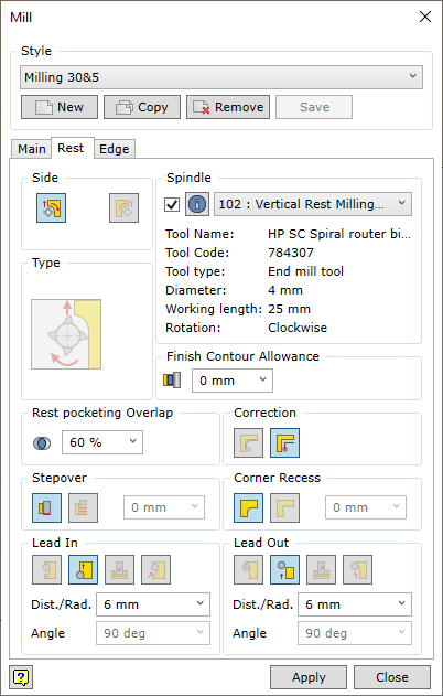

In the Spindle section, the spindle (and the tool) is selected from the drop-down list. The main information of the tool loaded on the spindle is provided below. In order to view full details of the spindle, click the information button  . The spindle data editing window is opened. In this window, the user can edit all data related to cutting modes (cutting feedrate, spindle rotation speed, etc.). Changed data can be saved. . The spindle data editing window is opened. In this window, the user can edit all data related to cutting modes (cutting feedrate, spindle rotation speed, etc.). Changed data can be saved.
Check box – indicates whether this sub-operation is included in the style being created.
|
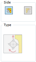
Spindle rotation direction is constant and depends on the shape of the loaded milling tool. The milling cutter should move relative to the surface in such a way that it does not damage the body of the part. Therefore, the tool path must be shifted in the distance of the radius of the tool with respect to the surface. This means that if the tool movement direction is changed, the movement direction for the milled contour is changed as well. At the same time, setting of the direction of the tool with respect to the processed contour also changes the milling method.

|
Conventional milling
|
Movement from the right with respect to the surface.
Considering that the tool is rotating clockwise.
|

|
Climb milling
|
Movement from the left with respect to the surface.
Considering that the tool is rotating clockwise.
|
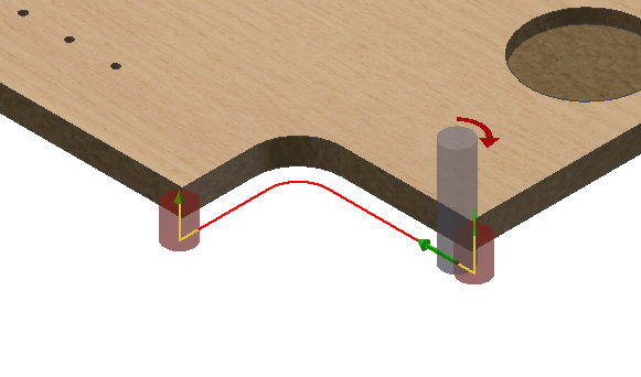 Climb Milling - frezavimas pagal pastūmą |
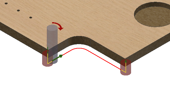 Conventional Milling - frezavimas prieš pastūmą
|
If the user does not select the movement direction of the tool with respect to the surface, the mill command automatically sets the movement direction so that climb milling is performed. This type of milling poses a lower risk of chipping a wooden part during milling. However, there are situations, where conventional milling is necessary. Therefore, the user may change the tool position with respect to the milled surface.
|

Rest milling can result in some areas where the tool performs the pocketing operation. This is where the overlap value of the tool is set. The value is set as a percentage of the tool diameter. The higher the percentage, the denser the trajectory of the pocketing.
|

Switches layer-by-layer contour milling on/off and allows the user to set the layer step.
 - Layer-by-layer milling off. - Layer-by-layer milling off.
 - Layer-by-layer milling on. - Layer-by-layer milling on.
If the layer-by-layer milling is on, the depth of one layer may be specified.
Important!
The operation of this option is not represented in the graphical display of trajectory, but it has an impact when generating the final CNC program. You can also see this when a simulation of the created CAM technology is running.
|

Assigning an oversize to the final pass of the rest milling tool. This oversize is in line with the oversize of the main tool passage. If the oversize of the main tool is not equal to 0, the final result of the operation will be an oversize left. For example, a 1 mm oversize is set for the main tool. For rest milling – 0.5 mm. The main tool will mill with 1+0.5=1.5mm oversize and the rest milling tool will mill 0.5mm. This will result in a final oversize of 1 mm.
|

Sets the type of adjustment for the rest milling tool. Read more about what this parameter means here.
|

Enables the tool path calculation option, which automatically detects the corners of the recessed path and performs milling. For more information on how this option works, click here.
|

These settings control how the tool approaches and withdraws from the trajectory when the milling is finished. For more information on available options, see here.
|
|
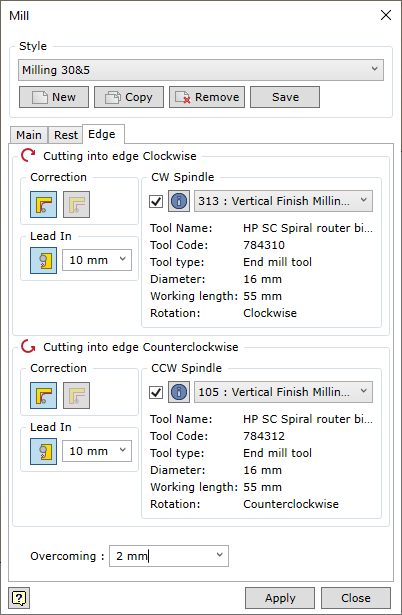
Cutting into edge Clockwise
|
Setting the tool parameters for cutting in clockwise.
|
Cutting into edge Counterclockwise
|
Setting the tool parameters for cutting in clockwise.
|
CW Spindle / CCW Spindle
|
Selecting the tool to execute the sub-operation.
|
Check box)
|
Indicates whether this sub-operation is included in the style being created.
|
Correction
|
Setting the type of trajectory calculation.
|
Lead In
|
Setting the size of the approach to the contour.
|
Overcoming
|
Determines the value of approach.
|
|
|


