Labeling

Top | Previous | Next


Accessed via the menu: Labelling


Woodwork for Inventor can export specific information about a part of a piece of furniture to a drawing. Autodesk Inventor symbols are used to display this information in a drawing. We will refer to these symbols as Labels. Such a label can be created as an Autodesk Inventor symbol and contain keywords displayed as Prompted Entry data fields. When generating a drawing, Woodwork for Inventor automatically places these labels in the appropriate locations. Keywords contained in such labels are interpreted and digital-textual information is derived appropriately.


All symbols necessary to set up Woodwork for Inventor drawings are stored in a Symbols.idw file that can be found in the following directory:

C:\Users\Public\Documents\Woodwork for Inventor\20223v13\Auto Plot Templates


Each properly configured Woodwork for Inventor drawing template in this file has references to the labels. In this way, changes to the appearance of any symbol or its keywords will affect all the generated files. The user can create their own file with their own symbols-labels and specify these when exporting labels to drawing templates. The user can add their own symbols to the Symbols.idw file.


This item describes which symbols correspond to which labels and how they will be placed in the drawing.
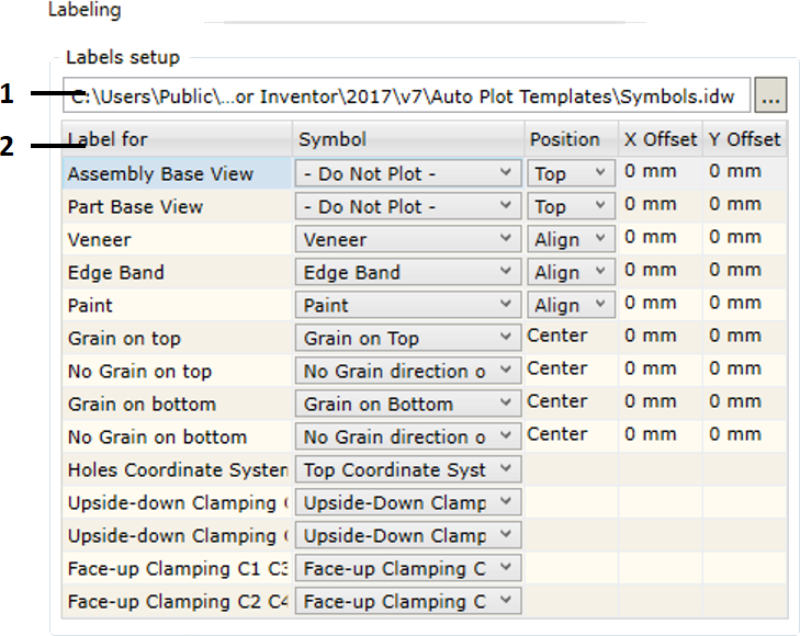
 

Labeling dialog


1.Select a (*.idw) file containing symbols required to represent label information. As mentioned above, the user may indicate a different file that contains symbols created by the user.


2.Area in which all possible label options are provided supporting the visualization of Woodwork for Inventor information in the drawing. Currently, the following labels of this type are available:
Assembly Base View: label for the export of the main assembly parameters: assembly code and assembly name. The label is only exported for the base view.
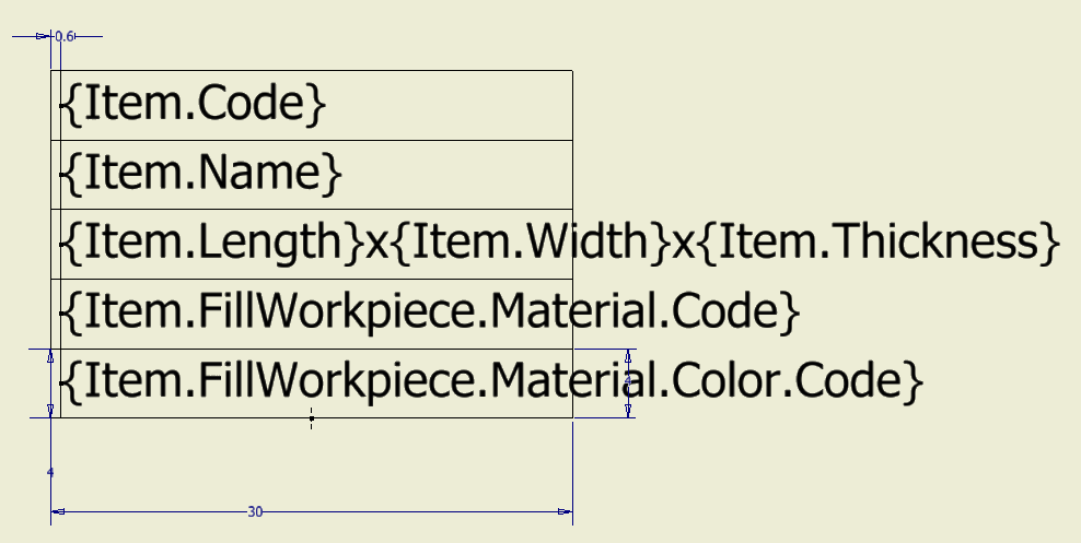
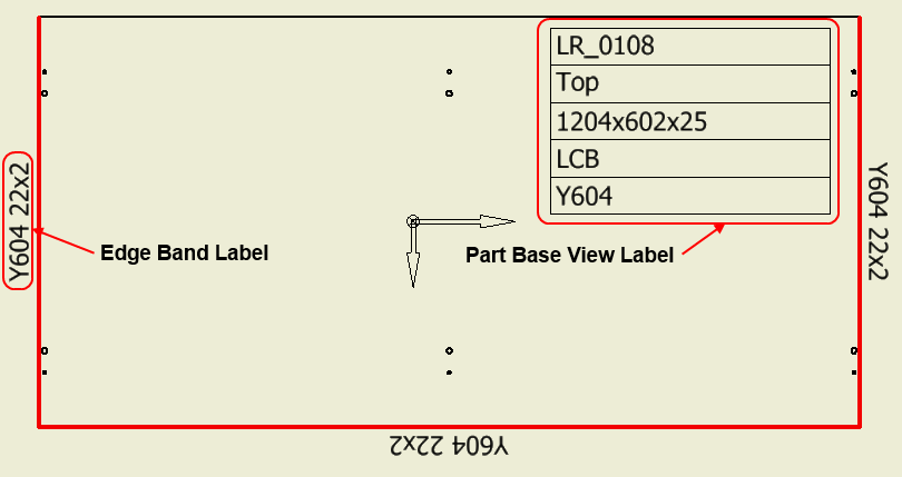
Part Base View: label for the export of the main part parameters: part code and part name, fill material name, dimensions, etc.
Veneer: label for the export of information about veneer/film material.
Edge Band: label for the export of information about edge band material.
Paint: label for the export of information about paint coating.
Grain on Top: a symbol representing the grain direction of the fill material where the main face of the part is pointed toward the observer. It is important in setting the right, left, front and back sides of the part. Click here for more information on this topic.
Grain on bottom: a symbol representing the grain direction of the fill material where the main face of the part is pointed away from the observer.
No Grain on Top: a symbol representing a direction based on which the workpiece size of the part is calculated if the main face of the part is pointed toward the observer.
No Grain on Bottom: a symbol representing a direction based on which the workpiece size of the part is calculated if the main face of the part is pointed away from the observer.
Holes Coordinate System: a symbol representing the starting point of the holes coordinate system based on which the coordinates of all holes to be placed in the holes table are calculated.
Upside-down Clamping C1 C3: a symbol representing the clamping of the part in corner 1 and 3 of CNC machine. The part in the drawing is clamped upside down.
Upside-down Clamping C2 C4: a symbol representing the clamping of the part in corner 2 and 4 of CNC machine. The part in the drawing is clamped upside down.
Face-up Clamping C1 C3: a symbol representing the clamping of the part in corner 1 and 3 of CNC machine. The part in the drawing is clamped face up.
Face-up Clamping C2 C4: a symbol representing the clamping of the part in corner 2 and 4 of CNC machine. The part in the drawing is clamped face up.


hmtoggle_plus1Symbol creation


As previously mentioned, each label type is associated with a drawing symbol selected from the symbol file. Symbols are created following the Autodesk Inventor rules. Also, Prompted Entry fields can be included in some label symbols. If the value of the field being included corresponds to the keyword of the Woodwork for Inventor BOM generator, the Auto Plot command, during the symbol insertion process, will interpret this field and take relevant data from the Woodwork for Inventor data stored in the part. Then this data will be placed to a relevant symbol field contained in the drawing.


The use of Prompted Entry fields during symbol insertion.


Using Prompted Entry fields, each label type can provide information about relevant Woodwork for Inventor data. The example below shows the symbol definition of the Part Base View label in the Symbols.idw file:


Auto Plot Symbol definition


Such symbol automatically placed in the drawing will look like this:


Auto Plot Labels


As you can see, the field values are read from the part data and placed in relevant symbol fields. On the left of the figure, an analogous Edge Band label symbol is circled which contains a material color field.


hmtoggle_plus1Fields used in label symbols


As you may notice, additional Prompted Entry fields in symbols are named similarly as in BOM templates. Depending on the label type, default fields may be used in symbols. Tables below show what fields can be used in symbols defining relevant label type.


Assembly Base View Label: label of the assembly base view projection.


Prompted Entry Name

Item.Code

Item.Name

Item.Type

Item.BomType


Part Base View Label: label of the part base view projection.


Prompted Entry Name

Item.Code

Item.Name

Item.Type

Item.BomType

Item.Length

Item.Width

Item.Thickness

Item.FillWorkpiece.Code

Item.FillWorkpiece.Name

Item.FillWorkpiece.Type

Item.FillWorkpiece.Length

Item.FillWorkpiece.Width

Item.FillWorkpiece.Thickness

Item.FillWorkpiece.Material.Type

Item.FillWorkpiece.Material.CountingType

Item.FillWorkpiece.Material.Length

Item.FillWorkpiece.Material.Width

Item.FillWorkpiece.Material.Thickness

Item.FillWorkpiece.Material.Code

Item.FillWorkpiece.Material.Name

Item.FillWorkpiece.Material.Color.Name

Item.FillWorkpiece.Material.Color.Code


Veneer, Edge Band, Paint: cover labels.


Prompted Entry Name

Item.Length

Item.Width

Item.Thickness

Item.Material.Type

Item.Material.CountingType

Item.Material.Length

Item.Material.Width

Item.Material.Thickness

Item.Material.Code

Item.Material.Name

Item.Material.Color.Name

Item.Material.Color.Code


Title Block: filling up fields of the title block.


Just like additional Prompted Entry fields can be included in a symbol, the same fields can be used in the Title Block description. For the title block, the same fields can be used as in the case of Assembly Base View and Part Base View labels.


hmtoggle_plus1Entering Woodwork for Inventor information in Title Block


Title Block can also be used to export information generated by Woodwork for Inventor.


Title Block Definition containing Woodwork for Inventor keywords

Title Block Definition containing Woodwork for Inventor keywords


Similar as with symbols, to do this, you will have to insert additional Prompted Entry fields in the Title Block Definition. All keywords that start with Item can be used here. When a drawing is generated (AutoPlot), Woodwork for Inventor information will be automatically exported to this block.


Title Block containing Woodwork for Inventor information

Title Block containing Woodwork for Inventor information


hmtoggle_plus1Label symbol positioning


Each Autodesk Inventor symbol has its own base point called Connection Point Grip. It is with respect to this point that symbol positioning in the drawing is defined. The definition of this position depends on the label type. We will look into possible positioning descriptions for each uniformly described label group.


Base view labels


These labels include:

Assembly Base View
Part Base View


In a drawing, these labels are positioned for the base view. The labels of this type can have a pre-defined position.


Etikeciu isnesimas projekcijai


As you can see in the figure above, repositioning values can be specified for the additional symbol position along X and Y directions, which will be calculated from the specified base point.


Cover marking labels


These labels include:

Veneer
Edge Band
Paint


The initial positioning point for these labels is found based on the cover reflecting the center-point of the curve.


Edge Band Label position


Symbol repositionings are performed with respect to this point, if such were specified by the user.


The Position option allows the user to specify label symbol alignment:

Align: label symbol which is aligned tangentially to the curve at the positioning point.
Not rotate: symbol which is always placed horizontally.


Grain direction labels

These labels include:

Grain on Top
Grain on bottom
No Grain on Top
No Grain on Bottom


These labels are placed in the center-point of the view projection. The user may specify the repositioning values for these labels from the center to X and Y directions.