System settings

Top | Previous | Next


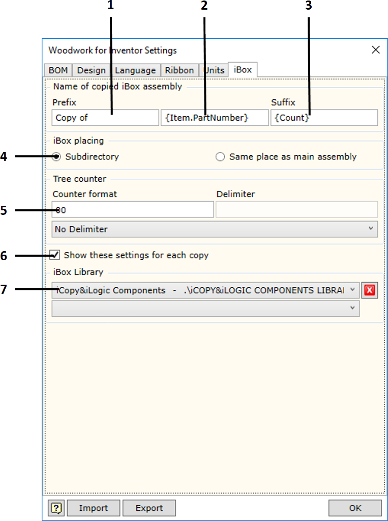
System settings allow the user to adjust the operation settings of the Woodwork for Inventor add-on


To open the command, go to:


Woodwork Design –> Help –> Settings settings32


The command has four tabs used to adjust the following operational aspects of Woodwork for Inventor:


hmtoggle_plus1BOM - Specification settings


BOM settings


Naming

Workpiece - fields for configuring the workpiece code and name. In Woodwork for Inventor, each part consists of workpieces (click here for more information). The values of these fields are generated using keywords and adding prefixes and suffixes.


<Part Code> - export of the code of the part, which includes the workpiece.


<PartName> - export of the name of the part, which includes the workpiece.


<Counter> - sequence counter.


<ACounter> - alphanumeric counter.


Multilayer - fields for configuring the name and code of a multilayer board workpiece.


Composite - fields for configuring the name and code of a composite (composed of other parts) part workpiece.


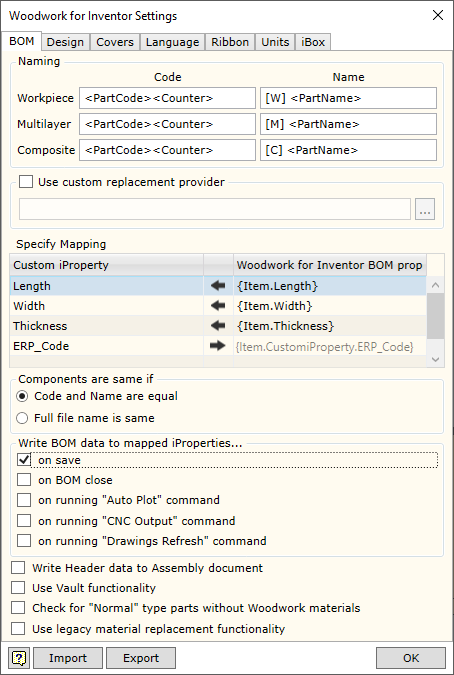
Use custom replacement provider - allows enabling/disabling the material replacement add-in developed by the user, which changes the standard material replacement procedure. File specification field is intended for indicating a .dll file, which implements the data retrieval method designed by the user.


Woodwork for Inventor has an option of writing different data created during BOM generation in parts from the geometry of which this data was calculated. For example, part length or part width. On the other hand, you can indicate to the system that the data entered in the part as Custom iProperty can be included in the BOM. This is done by providing a data field linking map in the Specify Mapping area.


In such case, desired data fields and their direction of movement should be registered in the table.


If you want to transfer data from the BOM to the part, first, in the Woodwork for Inventor BOMproperty column you have to enter a BOM keyword the value of which you want to export to the Customer iProperty field of the part. Once you enter the keyword, the data flow direction in this field automatically changes to Data move to right. In the Custom iProperty column, you must enter the name selected by the user and best describing the exported parameter. When Woodwork for Inventor BOM generator is used, the aforesaid Custom iProperty fields are automatically created for the part and the appropriate values are assigned to them.


If you want to use Custom iProperty parameter value in the BOM being generated, you have to register Custom iProperty as Woodwork for Inventor data. For this purpose, the desired field name has to be entered in the Custom iProperty column.  A keyword to access this field is automatically created in the Woodwork for Inventor BOM property column field. Once this keyword is entered in the desired location of the BOM template, Custom iProperty value will be exported to the BOM. Data flow direction will be from the part to the BOM. Data move to left.


The figure provided shows how the calculated part size is returned to the part Custom iProperty fields. In the last row, the data from the Custom Property table, for example, ERP_Code, may be included in the BOM using the keyword on the right.


Write BOM data to mapped iProperties

sets the moment of time for saving/updating Custom iProperties data field values, which are registered in the data linking table described above and generated by Woodwork for Inventor.

on save

saved at the moment of saving the file

on BOM close

saved at the moment of closing the BOM generator

on running "Auto Plot" command

saved at the moment of running the AutoPlot command

on runing "CNC Output" command

saved at the moment of running the CNC Output command

on runing "Drawing Refresh" command

saved at the moment of running the drawing refresh command


Additional control settings.


Write Header data to Assembly document

sets the option using which the data contained in the BOM are described as the BOM header so that they can be written to the assembly component. Later, this allows using the data in Woodwork for Inventor drawing templates by entering the appropriate keywords in the desired locations. AutoPlot command interprets these keywords and automatically exports the data to generated drawings.

Use Vault Functionality

allows enabling/disabling Woodwork for Inventor functionality used to integrate data in Autodesk Vault Professional. Woodwork for Inventor recognizes the project type and automatically enables the functionality used to automatically generate BOMs of an element containing Woodwork for Inventor data. When working with Autodesk Vault Basic, this functionality is not necessary, since integration at the file metadata level is sufficient. Integration at item data level causes problems, if this Autodesk Vault configuration is selected; therefore, there is an option that allows disabling this functionality.

Check for "Normal" type parts without Woodwork for Inventor materials

enables/disables checking for parts without an assigned Woodwork for Inventor material in an assembly. Such parts will not be included in Woodwork for Inventor specification. If the option is enabled, BOM generator gives a message with a list of such parts.


Use legacy material replacment functionality

enables/disables the use of the old material replacement dialogue.


hmtoggle_plus1General design settings in Woodwork for Inventor


W4INV Design Settings


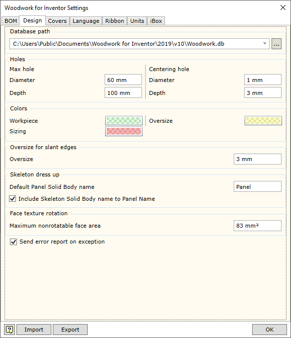
Materials Database path - specifies the location in which the Woodwork for Inventor material database is placed. Its default location is:

C:\Users\Public\Documents\Woodwork for Inventor\2022\v12\Materials.sdf


If several designers work for the same organization, it is recommended to keep a centralized database. If this is the case, the database will be stored on the server and will have the assigned path.


Holes

This section defines the hole parameters used for automatic creation of CNC technologies and hole tables for drawings.


Max Hole Diameter

The maximum diameter setting of cylindrical surface considered to be a hole. This parameter can also be accessed via the behavior settings of CNC technology generator.


Max Hole Depth

The maximum depth setting of cylindrical surface that is also considered to be a hole. This parameter can also be accessed via the behavior settings of CNC technology generator.


Centering Hole diameter

The hole diameter setting, which is also considered to be a centering drill operation. This parameter can also be accessed via the behavior settings of CNC technology generator.


Depth

Sets the drilling depth applied for centering operation. In this situation, the hole depth found in the model will not be taken into account. This parameter can also be accessed via the behavior settings of CNC technology generator.


Colors for represent

The section defines various colouring aspects, where it is necessary to support Woodwork for Inventor tasks.


Workpiece

Setting colour for the representation of workpieces, when working with Workpiece Oversize command.


Oversize

Setting colour for the representation of oversizes, when working with Workpiece Oversize command.


Sizing

Setting colour for the representation of sizing allowances, when working with Workpiece Oversize command.


Oversize for slant edges


Allows the user to specify the size to be added to the workpiece. If an edge of the part is obliquely bevelled, the edge lies on the side surface of the imaginary surrounding box of the workpiece. Click here for more information.

Skeleton dress up

The section defines parameters for automatic naming of part bodies in skeleton modelling.


Default Panel Solid Body Name

The root of the body name is entered here and automatically assigned to a new panel created in skeleton modelling.


Include Skeleton Solid Body name to Panel Name

Setting the option, which includes the name of the skeleton from which the panel is derived into the name of the panel.


Face texture rotation

Depending on the grain direction of the material, when working with materials, Woodwork for Inventor rotates the grain direction for each individual part face. This requires high capacity of the computer. The load can be adjusted by eliminating smaller faces from the rotation function or disabling the texture rotation function. The surface area which will not be subject to grain image rotation may be specified here.


hmtoggle_plus1Covers


Design Settings Covers


Highlight colors for covers and pre-mill allowance for edge banding

Determines the colour used to highlight edge bands depending on the edge band thickness, when the edge band highlighting functionality is activated in Material Assignment command. It is also possible to define automatically added oversizes for the workpiece here, if PreMilling is performed immediately before edge banding. Each edge band can be assigned individual pre-milling depth.


Thickness

Defining maximum thickness for the highlighting of the edge band using the selected colour.


Color

Specifying the colour.


Pre-Mill Alowance

Indicating the applicable size addition to the edge band of specified thickness, which is straight and coincides with the surrounding box edge. This addition is used when linear edge banding machine have an option of pre-milling immediately before edge banding.


Apply Pre-mill allowances for veneered edges too

Enables/disables interpreting the Veneer material the same as the Edge band for Pre-mill operation. This means that the Veneer on the sides of the part will affect the size of the workpiece.


Edge Band with

Controls the calculation of the edge band thickness.


Oversize for Range calculation

Allows specifying the oversize which will be added to the determined part thickness so that the calculated edge band width always exceeds the part thickness, including the oversize.


Woodwork for Inventor


Content of cover legend

Allows specifying the Legend content.


Text input row

Used to create the exported Legend keyword template.


Name

Inserts a keyword that exports cover material name into the template.


Code

Inserts a keyword that exports cover material code into the template.


Color Name

Inserts a keyword that exports cover material colour name into the template.


Color Code

Inserts a keyword that exports cover material colour code into the template.


Thickness

Inserts a keyword that exports cover thickness into the template.


Width

Inserts a keyword that exports cover width into the template.


Separator

Defines a separator that is used when descriptions of several types of edge bands have to be exported on the same side.


Coinsident to range box edge

Defines export of edges that coincide with the Surrounding Box. Export of this type of covers cannot be disabled.


Tangent to range rox edge

Defines export of tangent edges that coincide with the Surrounding Box.


Point touch range box edge

Defines export of point edges that coincide with the Surrounding Box.


Indirect touch range box edge

Defines export of indirect edges that coincide with the Surrounding Box.


Prefix/Sufix

Allows specifying a prefix or suffix for the exported information about each type of cover.


hmtoggle_plus1Language settings


In this section you may select the language for Woodwork for Inventor. To enable the selected language, you have to close and re-start the Autodesk Inventor program.


hmtoggle_plus1Ribbon - on/off of additional commands in a Woodwork Design ribbon


Additional Ribbon Tools


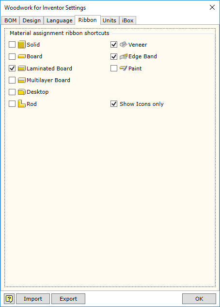
Allows enabling/disabling additional commands in Woodwork for Inventor toolbar, which facilitate the assignment of materials.


Show Icons Only - disables output of commands explaining items in the toolbar.


hmtoggle_plus1Units settings


In this window you will see a unit settings dialog presented in the form of a hierarchical tree structure.


Units are displayed in the form of a hierarchical tree. Unit settings selected in the higher level will apply to lower branches as well if not otherwise specified in the lower branch. The hierarchical tree is divided into the following levels:


The first level:

Display Units - units in which information is displayed on the screen.
Report Units - units in which information is displayed in the MS Excel reports.


The second level describes the following:

Fill Material - units for fill materials.
Cover Material - units for cover materials.


In the third level, you may adjust unit display for specific types of materials:

Solid
Board
Laminated Board
Multilayer Board
Rod
Tube
Desktop
Edge band
Veneer
Paint


In the fourth level, you may describe the following for each material type:

Length - length display.
Width - width display.
Thickness - thickness display.
Quantity - quantity display. Depending on the method of material calculation, quantity is displayed in the units of length, area or volume.


The user may save the settings to the external file and transfer them to the system.

The installation of the Woodwork for Inventor add-on offers the following two configurations:

ww4i imperial units.wunits - setting units of measurement  in the imperial system.
ww4i metric units.wunits - setting units of measurement in the metric system.


hmtoggle_plus1iBox components copying option


Design Settings iBox Setup


1.A prefix added to the file name of a copied iBox component. The prefix can include a counter keyword {Count} which means that a product with the name whose base matches the specified base will be searched in the directory in which the interior is designed. If this component is found, the counter value will be increased by one so that each iBox copy has an individual name.
2.A base of the file name of a copied iBox component. The user can specify the base every time they make copies of components. To do this, you will simply have to specify the name of the copy, for example, Corner cabinet. All sub-components of the iBox component will be named accordingly as if in a tree structure. So a part from iBox can be named Corner cabinet 01.ipt, etc. If you would like to avoid trouble of naming files every time you make copies, you can enter the component keyword that will be used for automatic naming. For example, if you enter a keyword {Item.PartNumber}, iProperty Part Number field of the iBox component will be read and used as the base when naming a copy of the iBox component. You can enter keywords that are used for the output of properties of assembly components to the specification.
3.A suffix added to the file name of a copied iBox component. The suffix can include a counter keyword {Count} which means that a product with the name whose base matches the specified base will be searched in the directory in which the interior is designed. If this component is found, the counter value will be increased by one so that each iBox copy has an individual name.
4.The user can choose a location for saving the iBox copy:
Subdirectory means that a directory will be created for each copy; the name of the directory will be the same as that of the file. The directory will be stored as a sub-directory within a directory containing the entire interior project.
Same place as main assembly means that files will be copied to the same directory in which the interior assembly is stored.


5.Counter format used when naming iBox sub-components. For more detailed information about the functioning of a counter based on a tree counter, see here.
6.You can disable this option every time you insert an iBox component. In such case, iBox copies will be created based on the rules specified in this window. These settings can also be adjusted when adjusting the general system settings.
7.Specifying a library directory containing iBox components and their parts. iBox Insert function knows that components stored in this directory have to be copied to the workspace of the project. Components included in an iBox assembly and stored in the library space but outside this directory will be Reused, not copied. These settings are saved for the current Autodesk Inventor project.