Shape nesting editing

Top | Previous | Next


Nesting Edit Ribbon


hmtoggle_plus1 Editing material sheets


Nesting Add New Sheet Icon

Add New Sheet

A new material sheet can be added to the current material worktop. Sheet dimensions are taken from the Woodwork for Inventor material database. These dimensions may be edited in the Properties tab of the side browser or cut according to piece instances arranged on the sheet.


Nesting Sheet Remove Icon

Delete Sheet

A material sheet can be removed from the current material worktop. Please note that parts arranged on the removed sheet will remain on the material worktop. Such parts are considered not arranged on the sheet and will not be represented in the CNC programs..


Nesting Crop Icon

Crop

The selected raw material sheet will be cut according to the arrangement of piece instances on the sheet.


Nesting Refit Icon

Refit

Rearrangement of parts according to the latest settings of the Nesting system. Rearrangement of the sheet selected by clicking the mouse or the whole worktop by default.


Nesting Flip Over Icon

Flip Over

Flipping the selected raw material sheet including all part instances arranged on the sheet.


hmtoggle_plus1Manipulating the part instances


Nesting Change start Point Icon

Start Point

Allows editing the starting point and cutting method of the nesting route of each part.


Nesting Start Point position Change


Icon meanings:


1.Current mill position. The direction of the teeth shows the direction of rotation.
2.Contour loop direction. Clicking the mouse on this icon changes the direction of the contour loop.
3.Indicator showing that the cutting tool approach will follow the ramp route. If there is no icon, the tool will approach vertically. The tool approach may be changed by selecting the ramp value in the dialogue box (see description below).
4.Indicator showing that the cutting tool withdrawal will follow the ramp route. If there is no icon, the tool will land vertically.
5.Icon showing the new position of starting point.


The command is sensitive to the cursor position on the screen. Hovering over the nesting route will mark it in green. This means that the start point will be changed for this particular contour. Mark the new starting point position using the mouse cursor.

Nesting Ramp Setup on Start Point


Setting tool approach


Together with the starting position, the approach of the tool until it reaches the working depth and its withdrawal from the material may be set. This can be done using the dialogue box. All setting options apply to the whole set of parts, which may be created by clicking on the middle of the part or using the instance assembly button Select All components. When a piece instance is included in the set, the background of the instance turns blue.


Direct approach Direct withdrawal - sets vertical approach/withdrawal of the tool to/from the starting point.


Ramp approch Ramp withdrawal - sets ramp approach/withdrawal of the tool to/from the starting point. The approach distance (viewed from above) has to be indicated in addition.


Nesting FlipOver Instance Icon

Flip horizontal

Flips the selected piece instance around the horizontal axis.

Nesting Flip Vertical Icon

Flip Vertical

Flips the selected piece instance around the vertical axis.

Nesting Rotate Instance 180 Icon

Rotate 180

Turns the selected piece instance around its center at an angle of 180 degrees.

Nesting Open In Inventor

Open

Opens the selected piece instance in Autodesk Inventor.


Manipulating the cursor using the context menu


A piece instance(s) may be managed using the cursor. This can be done in one of the following ways:


Creating a selection set

A set of instances may be created by selecting a part on the raw material sheet using the cursor. The changed colour of the part’s environment shows that the part has been selected. Several instances may be selected or removed from the set by holding CTRL key. Piece instances may be selected on the side browser. A set may be deleted by marking the space outside the raw material sheet using the cursor.


Changing the position of piece instance(s)

This can be done as follows:

1.Using the cursor click the LMB (left mouse button) and drag the set to the desired location.
2.Using the Grip. The selected piece instance(s) are enclosed in a surrounding box, which has control grips in four directions. Clicking on the selected grip carries the set of piece instances to the edge of the sheet or until it reaches another instance.


Nesting Instance Grips


Rotating the instance

An instance may be rotated on the plane of the sheet around the centre of the part. The rotation angle depends on the following factors:


1.If the material has a grain direction, the instance may be rotated only at an angle of 180 degrees. To do this, click the rotation icon in the right bottom corner of the surrounding box. Despite the rotation restrictions due to the material grain direction, rotating the instance is still possible. To do this, hold the SHIFT key and drag the rotation icon. The rotation will be done the same way as for a part without grain direction. Responsibility for this action lies with the user.


2.If the material does not have a grain direction, drag the rotation icon. The rotation will be done with the discretion specified in Nesting settings.


Copy of the instance

A piece instance may be copied using the Copy function in the context menu (RMB) or CTRL+V and pasted on the same sheet or another sheet. An instance cannot be pasted on the sheet of another worktop.


Deleting the instance

An instance may be deleted from the shape nesting scheme using the Delete function in the context menu (RMB) or DEL key.


Temporary removal of an instance from shape nesting

The selected instance is dragged outside the sheet using the cursor. Such instance will not be included in the final shape nesting CNC program. The instance may be returned to the sheet the same way.


hmtoggle_plus1Fixing a piece instance during nesting


When designing a shape nesting CAM technology for the sheet, it is essential that previously cut instances do not move while other instances are being cut. This is particularly important if a non-vacuum table is used. There are two ways to fix the instance during processing:


1.Fixing using bridges. This means that small bridges connecting the part with the sheet or adjacent instances are left around the perimeter of the piece instance.


2.Fixing using a thin layer of material, the so-called onion skin. When milling the outer contour of the instance, the mill does not go to the full depth of the part and leaves a thin layer of material.


Important! Only one of the above methods can be used for a material worktop. It is not possible to use bridges for one instance and onion skin for another instance on the same worktop. If the user wants to change the fixing method, the previously used method (for example, bridges) must be first completely removed, and only then the other fixing method (for example, onion skin) can be used.
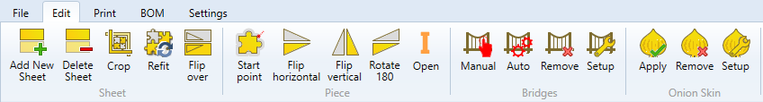


Nesting Manual Bridge control Icon

Manual

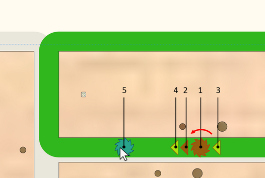
Allows placing the bridges manually. The command is sensitive to the cursor position on the screen. Hovering over the nesting route will mark it in green. This means that a new bridge will be made for this particular contour. Click LMB to create a bridge where the cursor is placed. A second click on the red circle removes the bridge..


Nesting Manual Bridge creation


Nesting Auto Bridge Icon

Auto

Carries out automatic replacement of bridges according to the settings provided during the initial inclusion of data or as provided in the current nesting settings (see Bridge Setup explanation below). Automatic replacement of bridges depends on the set created at the time of running the command:


If individual piece instances are selected, bridges will be created only for selected instances.
If a sheet is selected, bridges will be created for all instances on the sheet.
If the set is empty, bridges are created for all sheets on the material worktop.


Nesting Bridge Remove Icon

Remove

Removes the bridges. Removal of bridges depends on the set created at the time of running the command:


If individual piece instances are selected, bridges will be removed only from selected instances.
If a sheet is selected, bridges will be removed from all instances on the sheet.
If the set is empty, bridges are removed from all sheets on the material worktop.


Nesting Bridge Setup Icon

Setup

Setting the parameters of bridges.


Nesting Bridges setup


Max piece area to apply bridges

Sets the area of piece instances, for which automatic placement of bridges is applied during inclusion of data. Piece instances with a larger area are not included in the automatic placement of bridges. If automatic placement is used during nesting design, i.e. in the Nesting program, this restriction applies if:

A sheet is selected.
The set is empty.


If the user selects individual parts and runs automatic placement of bridges, this restriction is ignored.


Please note that if a bridge is placed for the selected piece instance, this means that a bridge will be automatically placed for the adjacent instance. This way the part position fixing is saved.
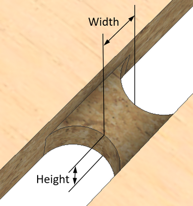
 

Bridge Width

Determines bridge width.


Bridge WidthxHeight


Bridge Height

Determines bridge height.


Bridge if margins is bigger than

Determines whether a bridge is necessary if the part is close to the edge of the sheet. If the distance from the part to the edge is greater than specified, the program will attempt to add a bridge.


Merge neighbor Piece bridges if distance is less than

If bridges on adjacent instances are placed at a distance smaller than specified, such bridges are automatically merged into one.


Minimum amount of bridge for Piece Instance

Specifies the minimum number of bridges to be created for each piece instance.


Nesting Onion Skin Apply Icon

Apply

Uses onion skin for the created set of piece instances in order to fix the position.


If the set consists of piece instances selected using the cursor, onion skin is applied for all selected parts. This is done despite the limitations provided in the onion skin settings (see Onion Skin Settings).
If the set consists of a raw material sheet, onion skin is automatically applied to all piece instances on the sheet. This is done in accordance with the limitations provided in the onion skin settings.
If the set is empty, onion skin is applied automatically to all piece instances on the material worktop. This is done in accordance with the limitations provided in the onion skin settings.


The yellow colour of the tool trajectory indicates that an instance has an onion skin.


Nesting Skin Onion trajectory


Nesting Onion Skin Remove Icon

Remove

Removes onion skin for selected piece instances. If the set is empty, onion skin is removed for all piece instances on the current raw material worktop.


Nesting Onion Skin Settings Icon

Setup

Sets the onion skin parameters.


Nesting Onion Skin setup


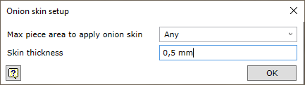
Max piece area to apply onion skin

Specifies the maximum area of the part for which onion skin is applied automatically. It is not applied for larger parts. “Any” means that onion skin will be applied to parts of any area, i.e. to all parts.


Skin thickness

Specifies the thickness of the onion skin.