For each part, the processing process starts from the selection of the CNC machine for which the technological operations will be created. Once the machine is selected, an information container-node (Job) will be automatically created in which information about part Clampings and technological operations will be placed. The selection of the machine is performed as follows:
Woodwork CAM -> Job ![]()
A dialog window will appear:
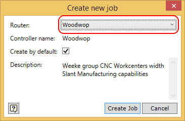
From the drop-down list (highlighted in red), select a Woodwop machine and, before clicking on the button “Create Job”, put a check mark next to “Create by default”. This check mark means that, when opening another part, an information container node (Job) will be automatically created for storing the technological operations created for the Woodwop machine. Here you can find a detailed explanation of the Job command. In future, the user may select a different CNC machine for which the processing operations will be generated by default or refuse the creation of processing operations by default altogether.
Once the information container for processing has been created, it is displayed in the side browser as shown in the figure below.
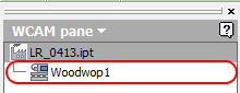
This node is currently empty. The next step is to create a part Clamping. During this process, the base point of the program to be created will be set. To facilitate the process, orient the part on the screen as shown in the figure below.
To open the (Clamping) command, go to:
Woodwork CAM -> Clamping ![]()
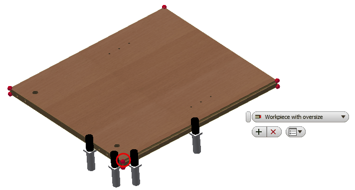
The command brings up the menu where the user may select the status of the part to be clamped to the machine at this processing stage. It may be a workpiece that has just been cut out of a board which carries along with it all pre-defined oversizes necessary for processing or it may be a part for which edge-banding operations have already been performed, etc. Here you can find more information about possible options for this command. From the drop-down list, select the option ![]() - "Workpiece with oversizes". While the command is active, the part is placed within the Range Box which represents the workpiece dimensions, and the red dots on the corners mark possible program base points. Select one of the possible part clamping base points in the way shown in figure above and click the "Apply"
- "Workpiece with oversizes". While the command is active, the part is placed within the Range Box which represents the workpiece dimensions, and the red dots on the corners mark possible program base points. Select one of the possible part clamping base points in the way shown in figure above and click the "Apply" ![]() button.
button.
The command creates a part Clamping information container.
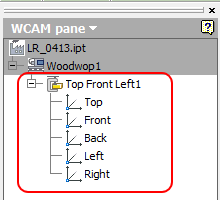
In this container, boundary representation of the workpiece is additionally created automatically for defining processing operations from different angles of the part. If you place the cursor over the board subnode, you can see the image of the boundary representation.