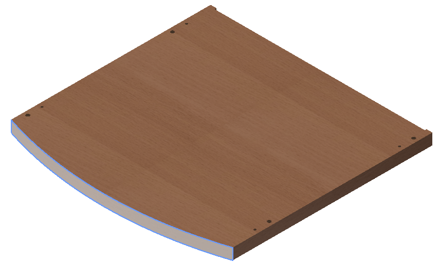
As with the previously processed part, first you have to set the base point.
Woodwork CAM -> Clamping ![]()
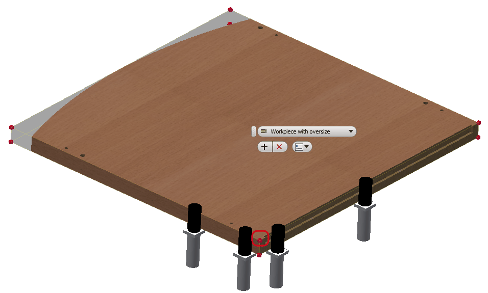
Orient the part in the way shown in the figure above and select the indicated angle of the part. Then click the "Apply" button.
Now that the base point of the part has been set, you can start the creation of processing operations. If everything has been created correctly, "Job" and "Clamping" tree nodes for relevant technological operations will be created in the side browser. The commands for creating operations become active and you can create a required CNC processing operation for the given part.
Now create the following technological operations for processing the part:
1. Groove cutting.
2. Milling of the front face of the part.
3. Hole drilling.
Woodwork CAM -> Groove
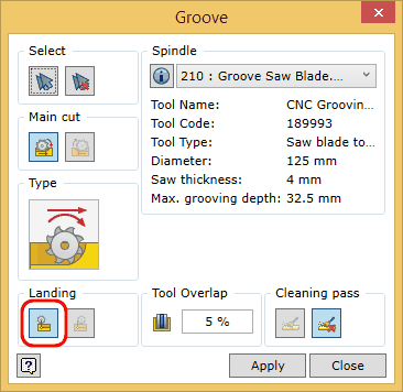
Use the automatic groove selection function
Click the "Apply" button. The operation has now been created. Close the dialog window of the Groove cutting command by clicking the "Close" button.
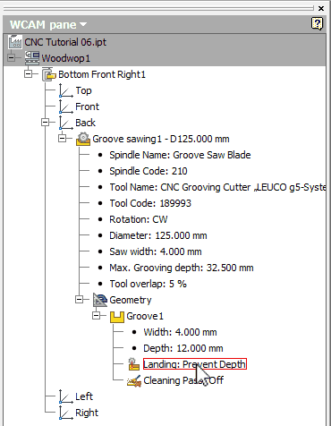
Place the cursor over the expanded tree node Landing of the Groove sawing operation as shown in the figure above. In the graphic view, you should now see the tool trajectory. Double click the left mouse button on the indicated node. You will see how the trajectory parameter changes from Prevent Depth to Prevent Length and at the same time you will see changes in the trajectory representation in the graphic view. In this way you can see that the operation settings can be changed after the operation itself has already been created. Select the blade entry option Prevent Depth.
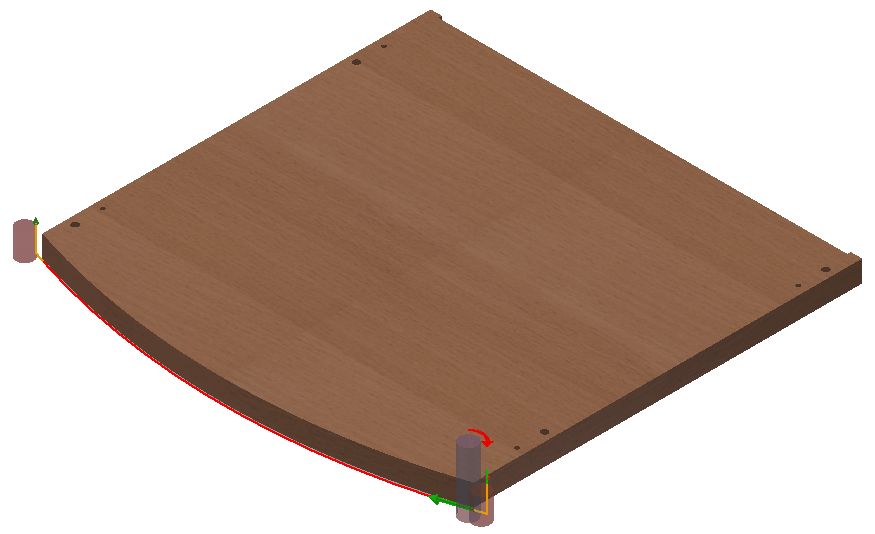
The next operation according to the plan is the milling of the front face of the part. Orient the part in the view screen so that the front face of the part is facing you.
|
Woodwork CAM -> Mill
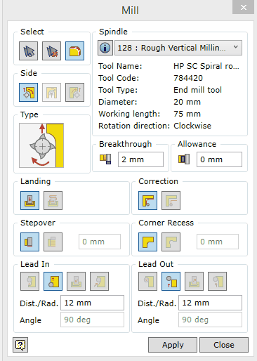
A dialog window of the Mill command will appear:
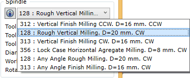
In the Spindle space, select the "128:Rough Vertical Milling. D=20 mm. CW" tool from the drop-down list as shown in the figure below.
Set the rest of the options as shown in the Mill command dialog window provided in the figure above. Here you can find information about the available Mill command setting options and their explanation. Click the button for the automatic selection of millable contours
For more information about geometry selection for the Mill command, click here. Click the "Apply" button. As with the previous operations, you will see that a Mill operation has been created in the Top face. If you place the cursor over it and expand it, in the graphic view you will see a tool trajectory that has been created.
Move the cursor over the Mill operation node Lead In trajectory and click a few times. In the screen, you will see a lead in trajectory edit menu.
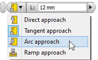
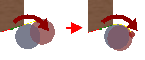
Click the drop-down list button and select the Arc approach option from the list. Then click the "Apply" button.
You will notice changes in the lead in trajectory of the tool. If you choose Tangent approach following the same steps, you will restore the previous lead-in trajectory which is suitable for this processing situation. |
To perform hole drilling, follow the same steps as you did for the previously processed part. Click Woodwork CAM -> and close the file of the current part. While closing the file, you will be asked if you want to save the recent changes to the file. Select the save option, otherwise the technology will not be saved.
Then return to the CNC "CAM Tutorial.iam" design environment.
|
