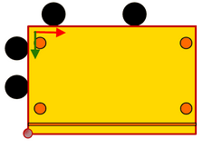
Concept

Top | Previous | Next


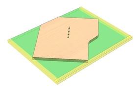
Before starting the processing of the part, the part is clamped into the machine as shown in the figure below.
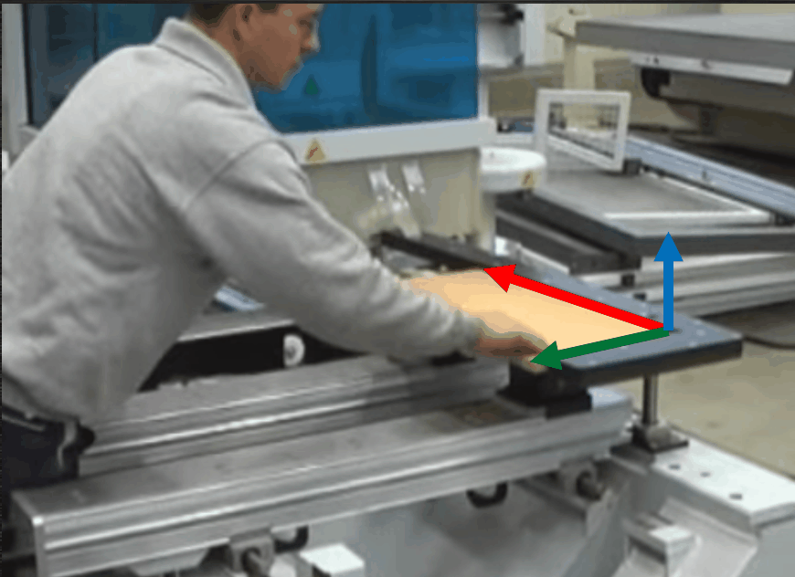
 

Clamping conception


This operation is usually performed following the cutting of the part workpiece from the raw material board. In this case it is not very important for the clamping of the workpiece at which corner it is clamped into the machine. It is crucial not to mix the longitudinal or transversal position of the workpiece in the machine. Depending on the operational procedure established within the company, the parts for which the Edge banding operations have already been performed can end up in the CNC centre. In this case it is important which corner of the part is clamped during the clamping operation. Therefore, it is important to take into account the following factors:


1.What state the workpiece is in when it reaches the machine into which this workpiece will be clamped.
2.Which corner of the workpiece is clamped in the corner with respect to the part shape.


hmtoggle_plus1Part coordinate system


For a better understanding of the explanation below, it is necessary to discuss the basic coordinate system of the part or of the part workpiece. With respect to this system, the clamping coordinate systems are determined and clamping corners are defined.


When assigning Woodwork for Inventor materials to the part model, algorithms are used to analyze the model shape and they interpret the top and bottom faces of the model, the right and left sides, etc. In other words, a basic coordinate system of the Woodwork for Inventor part is created. One should not confuse this system with the model coordinate system which can coincide or differ from the above-mentioned coordinate system. This is called automatic determination of the basic coordinate system of the Woodwork for Inventor part.


The user will see that this coordinate system has been determined immediately following the assignment of the Woodwork for Inventor material, after the use runs the Grain command grain_direction32 in the Woodwork Design branch. The user will then see (see fig. below) the coordinate system icon the direction of which corresponds to the grain direction, and the icon itself is placed in the Top plane. The user can change the basic (Top) plane of the part and the direction of the coordinate system by setting a Reference plane and changing the grain direction.


Note. If, during clamping, the same part and not the workpiece is used, the change of the grain direction will only change the calculation of the workpiece direction. In this case the grain direction will have no impact on the direction calculation (click here for more information).


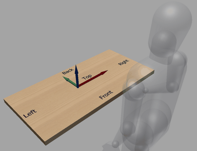
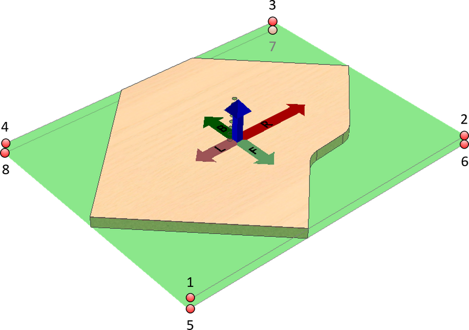
Thus, after changing the grain, the orientation of the basic coordinate system of the workpiece and of the part may differ. Depending on the type of object – a workpiece or a part which has already been processed – clamped into the machine, the sides of the part will be determined with respect to these coordinate systems. The figure below shows what is considered to be the top, the front, the back, the right and the left side of the part with respect to this coordinate system. With respect to this system, base points are numbered where part clamping can be requested.


It is important to know that after changing the grain direction or the Reference plane, it is interpreted that the CAM technology that has been created does not meet the basic coordinate system of the part. The technology with such clamping is marked with a lightning symbol in the browser and is ignored when outputting it to the CNC program. A possible solution to this situation is deleting and creating this clamping and again generating the processing operations within it.


Grain diretion and sides


hmtoggle_plus1Possible statuses of the part before executing a clamping operation


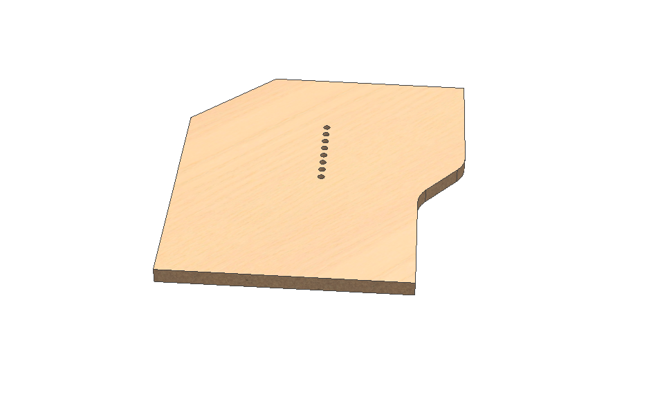
For the purpose of description we will use the example provided below.


Example for Clamping


The following status of the workpiece can be distinguished in the Woodwork for Inventor system:

Workpiece

Workpiece

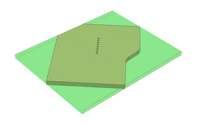
A part workpiece that surrounds the part shape with a rectangular parallelepiped (Surrounding box) which is oriented according to the grain direction of the material. The user may change the grain direction, at the same time changing the orientation and size of the part workpiece with respect to the model.

Workpiece Without covers and Without Oversize

Workpiece with Oversizes

Workpiece with oversize

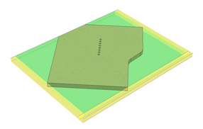
A part workpiece with defined oversize for contour machining. It is also oriented according to the grain direction of the material. The user may change the grain direction, at the same time changing the orientation and size of the part workpiece with respect to the model.

Workpiece Without Covers

Clamping object Workpiece with oversize and Top Bottom covers

Workpiece with Oversize and Top-Bottom Covers

Part workpiece with the defined overlaps for loop processing. The thickness of the workpiece includes thicknesses of both top and bottom coverings, if any. The workpiece is also arranged according to the pattern direction. The user can change the pattern direction; clamping of the part workpiece and its size in terms of the model will be changed at the same time.


Workpiece with Oversizes picture

Clamping object Workpiece with Top Bottom covers

Workpiece with Top-Bottom Covers

Part workpiece surrounding the part form as a Surrounding Box, arranged according to the pattern direction. The user can change the pattern direction; clamping of the part workpiece and its size in terms of the model will be changed at the same time. The thickness of the workpiece includes thicknesses of both top and bottom covers, if any.


Workpiece picture

Clamping Width Sizing oversize

Workpiece with Oversize and Sizing allowance


Part workpiece with set oversize and sizing allowance. The workpiece is also arranged according to the grain direction of the material. The user can change the grain direction; clamping of the part workpiece and its size in terms of the model will be changed at the same time.


Important!

This type of clamping is available only for parts with workpieces that have a sizing allowance.
Sizing is only possible with this type of clamping.
Once the sizing is performed, the option of clamping with sizing allowance is no longer available.


Workpiece Without covers With Oversize and Sizing

Clamping Workpiece with oversize and Sizing and Top Bottom covers

Workpiece with Oversize Sizing and Top Bottom Covers


Part workpiece with set oversize and sizing allowance. The workpiece is also arranged according to the grain direction of the material. The user can change the grain direction; clamping of the part workpiece and its size in terms of the model will be changed at the same time. The thickness of the workpiece includes thicknesses of both top and bottom covers, if any.


Important!

This type of clamping is available only for parts with workpieces that have a sizing allowance.
Sizing is only possible with this type of clamping.
Once the sizing is performed, the option of clamping with sizing oversize is no longer available.


Workpiece With oversize and Sizing

Part

Part without covers

A part with no additional covers. The parallelepiped surrounding the part is calculated according to the internal algorithm of the Woodwork for Inventor add-on. In this way, the longest edge of the part is found, and a coordinate system is oriented with respect to it.


If there is no such an edge, other algorithms for detecting a coordinate system are activated. The user does not have an option to change the direction of the coordinate system of the part. The user can only change the base plane of the part. This is done using the change grain direction command during which the Reference plane is changed.

Part without covers picture

Part with all covers

Part with all covers

A part with all covers. This includes Edge bands, Veneers and paint. The parallelepiped surrounding the part is calculated according to the internal algorithm of the Woodwork for Inventor add-on. In this way, the longest edge of the part is found, and a coordinate system is oriented with respect to it.


If there is no such an edge, other algorithms for detecting a coordinate system are activated. The user does not have an option to change the direction of the coordinate system of the part. The user can only change the base plane of the part. This is done using the change grain direction command during which the Reference plane is changed.

Part with all covers picture

Part with edge band covers

Part without bottom and top covers

A part with side covers. This means that  the part will have already been subjected to the Edge banding operation but the thickness of the top and bottom covers is not calculated.


The parallelepiped surrounding the part is calculated according to the internal algorithm of the Woodwork for Inventor add-on. In this way, the longest edge of the part is found, and a coordinate system is oriented with respect to it.


If there is no such an edge, other algorithms for detecting a coordinate system are activated. The user does not have an option to change the direction of the coordinate system of the part. The user can only change the base plane of the part. This is done using the change grain direction command during which the Reference plane is changed.


Part with edge banding without top and bottom covers

part with top bottom covers

Part without side covers

A part with only top and bottom covers. Side covers such as edge bands are not calculated.


The parallelepiped surrounding the part is calculated according to the internal algorithm of the Woodwork for Inventor add-on. In this way, the longest edge of the part is found, and a coordinate system is oriented with respect to it.


If there is no such an edge, other algorithms for detecting a coordinate system are activated. The user does not have an option to change the direction of the coordinate system of the part. The user can only change the base plane of the part. This is done using the change grain direction command during which the Reference plane is changed.

Part without side covers


hmtoggle_plus1Corner options for workpiece clamping


A part may be clamped using any of the four corners. Taking into account that the part can be flipped, we have four more corners that can be clamped in the clamping device. Thus, we have 8 potential base points.


The figure below shows these potential clamping corners. When clamping the workpiece for CNC processing, the corners are numbered according to the orientation of the workpiece coordinate system. When clamping the part, the system calculates the coordinate system and the points are arranged according to it. These corner numbers are used in Woodwork for Inventor internal mechanisms, but may also be transferred to Woodwork for Inventor BOM reports. It is also possible to inform the user which corner of the part is the base point in CNC processing. The image below shows the clamping of a workpiece.


Clamping points


hmtoggle_plus1Corner for clamping the workpiece to the machine


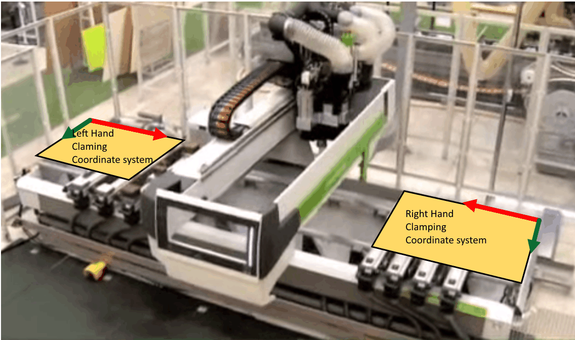
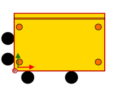
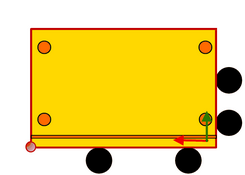
Some woodworking machines have an arrangement which, while performing the processing of a workpiece in one side, allows clamping a workpiece of another part in the other side. As shown in the figure below, in this case the clamping corner will change and at the same time the type of the coordinate system will change from the right-handed to the left-handed. This, in turn, means that the coordinates in the CNC program will be recalculated.


Clamping corner


The decision as which side of the machine the workpiece should be clamped to is usually made by the machine operator because the technologist-programmer does not know at which moment in a production flow a particular part will arrive at the machine and which side of the machine will be unoccupied. Therefore, the machine software usually provides for a simple procedure which converts the data in the coordinate system of the given program from right to left and vice versa. In this way the operator can easily use the same CNC program and work at any chosen side of the machine.


However, there exists machines that use a left-handed coordinate system as the base coordinate system, thus the Woodwork for Inventor CAM module has an option allowing the user to specify which corner of the machine the part will be clamped to and which coordinate system will be used.


There are four available options:


Lower Right corner

Front Left

Front left

Lower right cornerr

Front Right

Lower Right

Upper Right corner

Back Right

Back Right

Left upper

Back Left

Upper Left


By default, the Woodwork for Inventor CAM module interprets that the part is clamped at the Front Left corner. One should bear in mind that the front, the back, the right and the left side are specified with respect to the part coordinate system.


The CAM processing of the part may have one, two or more clampings. When creating CAM technological operations, only one clamping can be active.