System settings

Top | Previous | Next


System settings allow the user to adjust the operation settings of the Woodwork for Inventor add-on


To open the command, go to:

Woodwork Design –> Help –> Settings settings32


The command has four tabs used to adjust the following operational aspects of Woodwork for Inventor:


hmtoggle_plus1 BOM - Specification settings


BOM settings


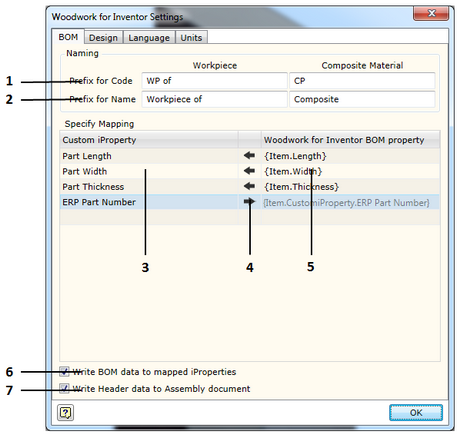
1. Prefix for Code - sets prefix for the code.

Workpiece - field used to indicate a desired prefix for the workpiece code. In Woodwork for Inventor, each part consists of workpieces (click here for more information). These workpieces automatically acquire the same code as that of the part including an additional prefix the meaning of which is entered in the field described herein.

Composite Material - field used to indicate a desired prefix for the code of the part workpiece glued from other parts. Woodwork for Inventor part workpieces can be designed from several parts consisting of workpieces (click here for more information). These workpieces automatically acquire the same code as that of the material assigned to it including an additional prefix the meaning of which is entered in the field described herein.

2. Prefix for Name - sets prefix for the name.

Workpiece - field used to indicate a desired prefix for the workpiece name. In Woodwork for Inventor, each part consists of workpieces (click here for more information). These workpieces automatically acquire the same name as that of the part including an additional prefix the meaning of which is entered in the field described herein.

Composite Material - field used to indicate a desired prefix for the name for the part workpiece glued from other parts. Woodwork for Inventor part workpieces can be designed from several parts consisting of workpieces (click here for more information). These workpieces automatically acquire the same name as that of the material assigned to it including an additional prefix the meaning of which is entered in the field described herein.

Woodwork for Inventor has an option of writing different data created during BOM generation in parts from the model of which this data was calculated. Examples would include part length or part width.  On another hand, you can indicate to the system that the data written in the part as Custom iProperty can be included in a BOM. This is performed by providing a data field linking map in the Specify Mapping area.

If you want to transfer data from the BOM to the part, first, in the Woodwork for Inventor BOM property column (seen as number 5 in the figure) you have to enter a BOM keyword the value of which you want to export to the Customer iProperty field of the part. Finally, in the Custom iProperty column (seen as number 3 in the figure), you must enter the name selected by the user which best describes the exported parameter. The aforementioned fields are created automatically in the part.
If you want to do the opposite, you need to take a Custom iProperty parameter and use it in the BOM being generated. In this case you first need to enter a parameter name in the Custom iProperty field which exists in the components and set data direction from the component to the BOM. The program will automatically create a keyword in the Woodwork for Inventor BOM property column field which will be linked to such datum and it will help generate the value of this datum from the BOM template.

The figure provided shows how the calculated part size is returned to the part Custom iProperty fields. In the last line, the datum from the ERP system may be included in the BOM using the keyword on the right.

6. Write BOM data to mapped iProperties – sets the option which, at the time of closing the Woodwork for Inventor BOM generator, writes values for the components generated during the operation of the BOM generator in the fields created by the user (Custom iProperties). Such option is left in order for the user to be able to turn off the writing of data to the said fields each time the user closes the BOM generator in case the user’s computer has weaker configuration.

7. Write Header data to Assembly document - sets the option using which the data contained in the BOM and described as a BOM header can be written to the assembly component from which the BOM itself was generated. This allows exporting this data to drawings after starting the Auto Plot function.


hmtoggle_plus1 
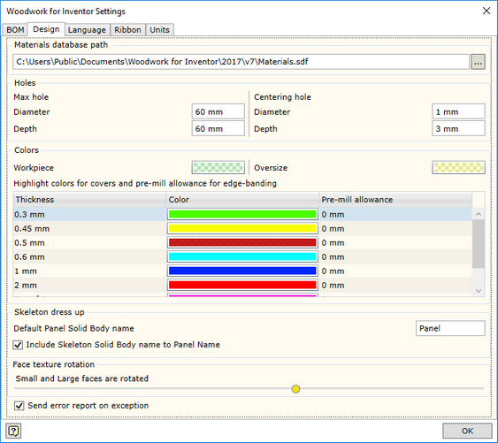
Design settings in Autodesk Inventor


W4INV Design Settings


Materials Database path - specifies the location in which the Woodwork for Inventor material database is placed. Its default location is:

C:\Users\Public\Documents\Woodwork for Inventor\V7\Materials.sdf


If several designers work for the same organization, it is recommended to keep a centralized database. If this is the case, the database will be stored on the server and will have the assigned path.


Holes

This section defines the hole parameters used for automatic creation of CNC technologies and hole tables for drawings.


Max Hole Diameter

The maximum diameter setting of cylindrical surface considered to be a hole. This parameter can also be accessed via the behavior settings of CNC technology generator.


Max Hole Depth

The maximum depth setting of cylindrical surface that is also considered to be a hole. This parameter can also be accessed via the behavior settings of CNC technology generator.


Centering Hole diameter

The hole diameter setting, which is also considered to be a centering drill operation. This parameter can also be accessed via the behavior settings of CNC technology generator.


Depth

Sets the drilling depth applied for centering operation. In this situation, the hole depth found in the model will not be taken into account. This parameter can also be accessed via the behavior settings of CNC technology generator.


Colors

This section defines various coloring aspects, where it is necessary to support Woodwork for Inventor job.


Workpiece

Sets the color for the representation of workpieces, when working with Workpiece Oversize command.


Oversize

Sets the color for the representation of oversizing, when working with Workpiece Oversize command.


Highlight colors for covers and pre-mill allowance for edge banding

Setting color used to highlight edge bands, depending on the thickness of edge band, when the edge band highlighting is activated in the Material Assignment command. It is also possible to define automatically additional oversizing for the workpiece here, if the pre-mill is performed immediately before edge banding. Each edge band can be assigned an individual pre-milling depth.


Thickness

Defines the maximum thickness for the highlighting of the edge band using the selected color.


Color

Defines the color.


Pre-Mill Alovance

Defines the applied oversize for the workpiece edge banded with the edge band of the specified thickness.


Skeleton dress up

This section defines parameters for automatic naming of part bodies in skeleton modeling.


Default Panel Solid Body Name

Entering the base of a body name, which will be automatically be assigned, when a new panel is created using skeleton modeling.


Include Skeleton Solid Body name to Panel Name

Setting an option, which includes the name of skeleton, to which the panel belongs, in the panel name.


Face texture rotation

Depending on the texture direction of the material, when working with materials, Woodwork for Inventor rotates the texture for each individual part face. This requires high capacity of the computer. The load can be adjusted by eliminating smaller faces from the rotation function or turning off the texture rotation function. The further to the left you move the scroll box, the larger faces are eliminated from the rotation algorithm.

hmtoggle_plus1 Language settings


In this section you may select the language for Woodwork for Inventor. To enable the selected language, you have to close and re-start the Autodesk Inventor program.


hmtoggle_plus1 Units settings


In this window you will see a unit settings dialog presented in the form of a hierarchical tree structure.


Units are displayed in the form of a hierarchical tree. Unit settings selected in the higher level will apply to lower branches as well if not otherwise specified in the lower branch. The hierarchical tree is divided into the following levels:


The first level:


Display Units - units in which information is displayed on the screen.
Report Units - units in which information is displayed in the MS Excel reports.


The second level describes the following:


Fill Material - units for fill materials.
Cover Material - units for cover materials.


In the third level, you may adjust unit display for specific types of materials:


Solid
Board
Laminated Board
Multilayer Board
Rod
Tube
Desktop
Edge band
Veneer
Paint


In the fourth level, you may describe the following for each material type:


Length - length display.
Width - width display.
Thickness - thickness display.
Quantity - quantity display. Depending on the method of material calculation, quantity is displayed in the units of length, area or volume.


The user may save the settings to the external file and transfer them to the system.

The installation of the Woodwork for Inventor add-on offers the following two configurations:

ww4i imperial units.wunits - setting units of measurement  in the imperial system.
ww4i metric units.wunits - setting units of measurement in the metric system.