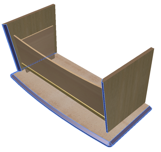
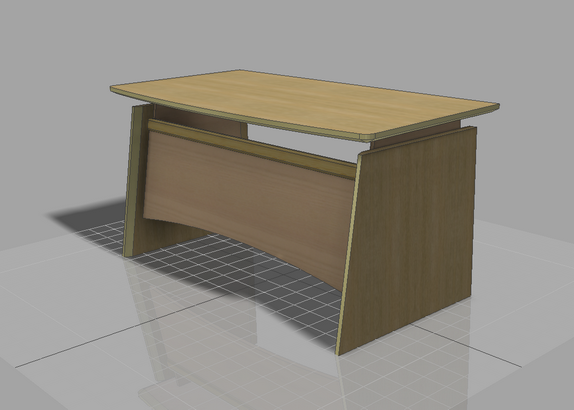
This section describes how to assign materials to table components.
If you restart Autodesk Inventor after closing it, you will find your unfinished assembly model under the name TBL.iam in the project workspace catalogue Samples/My Table.
To open the material assignment command, go to:
Woodwork Design –> Material –> Assign ![]()
A material assignment dialog window will appear.
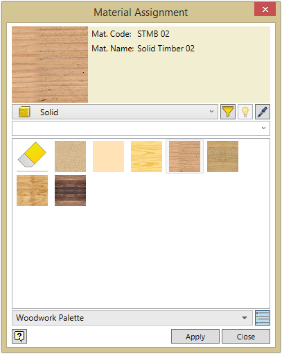
If the image you see is different from the one shown in this example, click ![]() button and enable icon-based material representation.
button and enable icon-based material representation.
Note: Due to continuous software updates, the content of the Woodwork for Inventor material data bases and dialogue boxes used by the program may be different from the images provided in this guide.
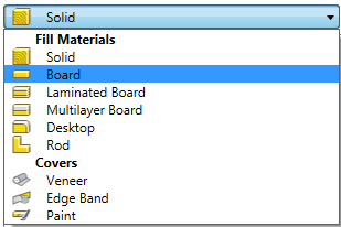
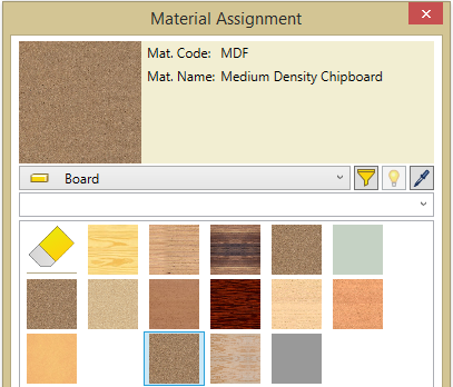
In the material type window, select Board type material.
The space in the bottom of the window is filled with the palette entries for the Board type material. Select the palette entry with a MDF material. In the current entry window, you will see complete information about this material, its code and name.
Leave the material assignment command window open, and, using the cursor, indicate the parts you intend to assign the selected material to and click the “Apply” button.
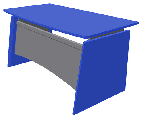
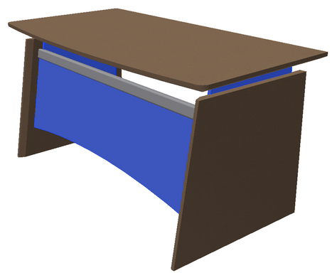
The default color of the components specified within the model is changed into the MDF board color.
|
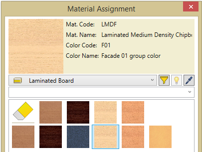
In the material type window, select Laminated Board section. Then, in the palette item area, select the laminated board palette item LMDF with color coating F01 for the façade.
Select components within the furniture model to which this item will be assigned and click the “Apply” button.
|
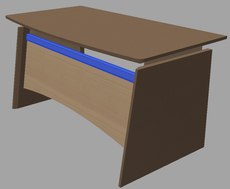
In the material type window, select a Rod type material section. Then, in the palette item area, select wood beam TMB type material.
Select the shown component in the furniture model and click the "Apply" button.
|
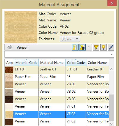
In the material type window, select a Veneer type material. To try a different palette visualization style, click the bottom button in the dialog window.
Now you can see that palette entries are represented in the form of a table. Select a Veneer item with a color code VF 02.
In the furniture model, select the top surface of the desktop and all surfaces of the table legs (except for the bottom and the front). Click the “Apply” button.
Select PF; Paper Film palette item and apply paper film to the bottom surface of the desktop.
|
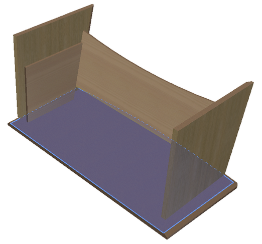
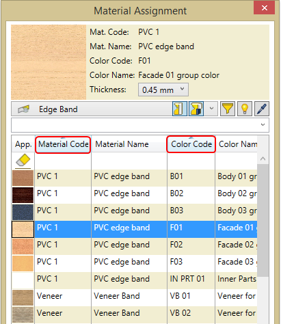
In the material type window, select Edge Band type material. Sort entries by material and color code. To do this, put the cursor on the Material Code column and left-click on it. You will see that all the palette entries are at once arranged in the alphabetical order based on the values of this column. Press and hold "Shift" and use the cursor to select the heading of the Color Code column. You will see that entries are sorted in the alphabetical order based on the values of the Material Code and Color Code columns.
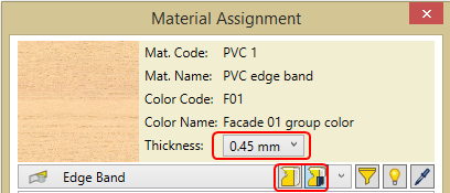
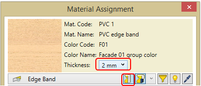
Select a palette item named PVC1;F01. In the current palette item Thickness field, select edge band thickness of 0.45 mm. Additionally, set edge band position with respect to the component model. Select Cover position on top One more thing you have to indicate is Overwrite cover position
Indicate all surfaces that need to be covered with the selected edge band and click the “Apply” button.
Click the Select a new edge band thickness of 2mm.
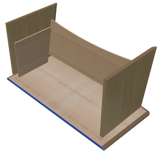
Select the desktop edge in the model and click the “Apply” button.
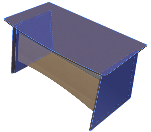
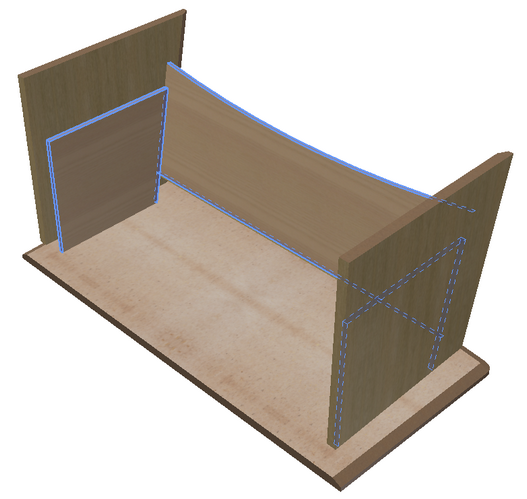
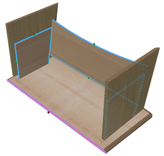
Now check the thickness and grain direction of the edge bands placed in the model. To do this, click the
To disable edge band highlighting, click the highlighting button again.
|
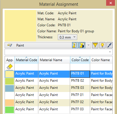
In the material type window, select Paint material type. Sort paint by material and color code, just like with edge banding in the previous section. Select Acrylic Paint - PNTB 01 color type.
Select surfaces you want to apply paint to and click “Apply”.
Your work should look like this at this stage.
To save your work, press "Ctrl+S". |
