System settings allow the user to adjust the operation settings of the Woodwork for Inventor add-on
To open the command, go to:
Woodwork Design –> Help –> Settings ![]()
The command has four tabs used to adjust the following operational aspects of Woodwork for Inventor:
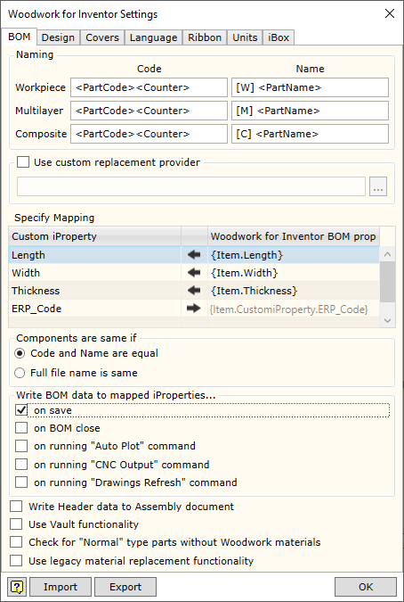
Use custom replacement provider - allows enabling/disabling the material replacement add-in developed by the user, which changes the standard material replacement procedure. File specification field is intended for indicating a .dll file, which implements the data retrieval method designed by the user.
▪Woodwork for Inventor has an option of writing different data created during BOM generation in parts from the geometry of which this data was calculated. For example, part length or part width. On the other hand, you can indicate to the system that the data entered in the part as Custom iProperty can be included in the BOM. This is done by providing a data field linking map in the Specify Mapping area.
In such case, desired data fields and their direction of movement should be registered in the table.
▪If you want to transfer data from the BOM to the part, first, in the Woodwork for Inventor BOMproperty column you have to enter a BOM keyword the value of which you want to export to the Customer iProperty field of the part. Once you enter the keyword, the data flow direction in this field automatically changes to
▪If you want to use Custom iProperty parameter value in the BOM being generated, you have to register Custom iProperty as Woodwork for Inventor data. For this purpose, the desired field name has to be entered in the Custom iProperty column. A keyword to access this field is automatically created in the Woodwork for Inventor BOM property column field. Once this keyword is entered in the desired location of the BOM template, Custom iProperty value will be exported to the BOM. Data flow direction will be from the part to the BOM.
The figure provided shows how the calculated part size is returned to the part Custom iProperty fields. In the last row, the data from the Custom Property table, for example, ERP_Code, may be included in the BOM using the keyword on the right.
Additional control settings.
|
|
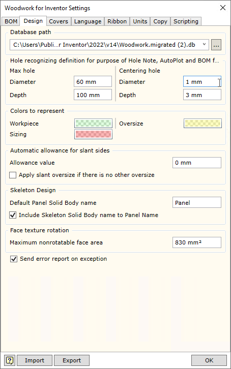
Materials Database path - specifies the location in which the Woodwork for Inventor material database is placed. Its default location is: C:\Users\Public\Documents\Woodwork for Inventor\2025\v15\Materials.sdf
If several designers work for the same organization, it is recommended to keep a centralized database. If this is the case, the database will be stored on the server and will have the assigned path.
|
|||||||||||||||||||||||||||||||||||||||||
|
Woodwork for Inventor
|
|||||||||||||||||||||||||||||||||||||||||||||||||||||||||||||||
In this section you may select the language for Woodwork for Inventor. To enable the selected language, you have to close and re-start the Autodesk Inventor program.
|
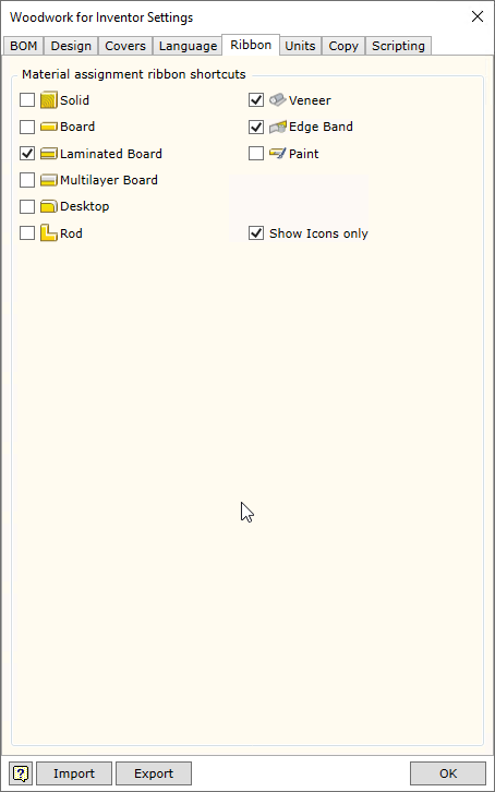
Allows enabling/disabling additional commands in Woodwork for Inventor toolbar, which facilitate the assignment of materials.
Show Icons Only - disables output of commands explaining items in the toolbar.
|
|
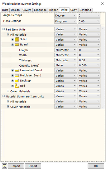
In this window you will see a unit settings dialog presented in the form of a hierarchical tree structure.
Units are displayed in the form of a hierarchical tree. Unit settings selected in the higher level will apply to lower branches as well if not otherwise specified in the lower branch. The hierarchical tree is divided into the following levels:
The first level: ▪Display Units - units in which information is displayed on the screen. ▪Report Units - units in which information is displayed in the MS Excel reports.
The second level describes the following: ▪Fill Material - units for fill materials. ▪Cover Material - units for cover materials.
In the third level, you may adjust unit display for specific types of materials: ▪Solid ▪Board ▪Laminated Board ▪Multilayer Board ▪Rod ▪Tube ▪Desktop ▪Edge band ▪Veneer ▪Paint
In the fourth level, you may describe the following for each material type: ▪Length - length display. ▪Width - width display. ▪Thickness - thickness display. ▪Quantity - quantity display. Depending on the method of material calculation, quantity is displayed in the units of length, area or volume.
The user may save the settings to the external file and transfer them to the system. The installation of the Woodwork for Inventor add-on offers the following two configurations: ▪ww4i imperial units.wunits - setting units of measurement in the imperial system. ▪ww4i metric units.wunits - setting units of measurement in the metric system.
|
|
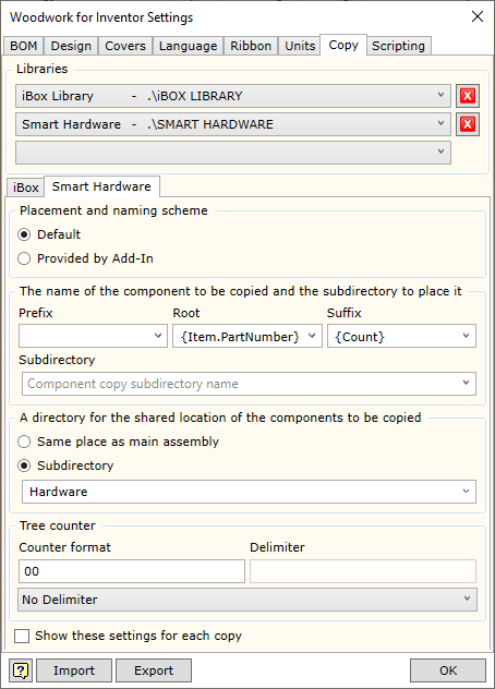
Woodwork for Inventor automatically copies two types of components during operation: iBox and Smart Hardware. Each of these types can have their own settings for how they are renamed and where they are to be copied to during copying.
|
||||||||||||||||||||||||
|
When developing Java Script Macro programs, it is convenient to use the freely available Microsoft editor Visual Studio Code to debug them. It needs to be registered with the system for it to work successfully. To do this, you need to install the Visual Studio Code editor and in the Woodwork for Inventor plug-in, specify where on the disk it is installed. In addition, you need to specify the port of the connection to the application, which is by default assigned to port 57154.
|
