The spindle is a part of the machine into which a tool is mounted and this part imparts a working movement to the tool. This movement is required to perform material removal or augmentation of a part workpiece. There is usually one spindle in a metal processing machine and the tool setup for this spindle can be changed. This change can be performed by a machine operator or by using special Magazines with different tool change mechanisms. The characteristics of one spindle are determined by the amount of forces used for metal cutting and by the required accuracy of processing.
Meanwhile, woodworking does not require such amount of cutting forces and the accuracy requirements are less strict, thus in order to ensure a more effective and quicker woodworking process, machining centers have been created which are markedly different from those of metal processing machines. In terms of the machining centre, woodworking machines are much more complex. The moving machine head may contain tens of spindles with different spatial orientation and with tools of different purpose attached to them. Such a machining centre allows a very fast completion of a series of operation without the need to waste time changing the tools. In addition, more complex machines are capable of efficiently using a special Magazines tool change method. Thus we have a situation where all this variety of spindles have to be described for a given machine.
Further we will discuss what characteristics describe the spindle.
Information identifying the spindle
The spindle must have a specific name in the database. To name it, the following two fields identifying the spindle are used:
| ▪ | Name: spindle name. Here, the user enters the name that briefly and efficiently describes the purpose of the spindle. |
| ▪ | Code : spindle code. This code usually corresponds to the number of the tool in the machine. Throughout the entire information processing chain, this number is included in the final program text as a command in the tool start and tool use command. For example, T01, T12, etc. |
The combination of these two fields must be unique in the data of the given tool. In other words, the same tool code can be used for multiple tools if the names of these tools are different and vice versa, but there cannot be several tools with the same name and same code in the same machine.
Tool used for setting up the spindle
Each spindle must be set up with a tool selected from a Tool Pool. All spindles are grouped according to the type of the tool installed in them:
![]() Spindles set up with Through Drill tools
Spindles set up with Through Drill tools
![]() Spindles set up with Blind Drill tools
Spindles set up with Blind Drill tools
![]() Spindles set up with End Mill tools
Spindles set up with End Mill tools
![]() Spindles set up with Saw Blade tools
Spindles set up with Saw Blade tools
When entering spindle data, there is a moment where the spindle that has been created does not have a tool assigned to it and it is only an abstract spindle. Such a spindle falls within the tool-less group where the spindle does not have a tool assigned to it. Once a tool has been assigned to the spindle, such a spindle is automatically transferred to the group based on the tool installed in it. It is important to know that the characteristics entered about the spindle differ depending on the group it belongs to.
Cutting modes
The cutting modes of the tool are defined by a feed rate and a spindle rotation speed. These characteristics are present in all spindle groups:
| ▪ | Cutting feedrate is the speed at which the cutter moves with respect to the work material. It is expressed in mm/min in metric units, and inch/min in imperial units. |
| ▪ | Rotation Speed is the rotation speed of the spindle. It is expressed in revs/min. |
Other cutting mode characteristics depending upon the spindle group
![]() Characteristics of the
Characteristics of the ![]() Through Drills and Blind Drills spindle group:
Through Drills and Blind Drills spindle group:
Tool specifying is a characteristic defining how the tool is specified when identifying it in the CNC program. In some front-end CAM systems, drills can be specified indirectly, i. e. there is no need to specify the number of a particular spindle; it is simply enough to specify a drill diameter for a given operation. The front-end CAM system itself selects required tools based on the tool setup configured in the machine. Such a process is more convenient in the chain where the technologist-programmer also acts as a machine operator. The machine operator has a greater freedom to manipulate the spindle setup. Therefore, taking into account the machine for which configuration is being created, there are two ways for indicating tool specification:
| 1. | By Code: the tool that is being output in the CNC program is the one that is specified in the spindle code. |
| 2. | By Diameter: no particular tool is specified in the CNC program; only its diameter is specified. |
Tool withdrawal feed-rate is the speed at which the tool is withdrawn. For some CNC machines, it is necessary to specify at what speed the drill is withdrawn after the operation is completed. It is usually left unspecified.
![]() Characteristics of the End Mill spindle group
Characteristics of the End Mill spindle group
| ▪ | Tool direct landing feedrate: the feedrate of the direct landing of the tool to the material. This is a feedrate at which the mill moves downwards where the landing to the material is done in a straight downward movement. |
| ▪ | Tool orbit landing feedrate: the feedrate of the orbit landing of the tool to the material. |
| ▪ | Tool approach to contour feedrate: the feedrate at which the tool approaches the contour being milled. |
| ▪ | Tool withdrawal from contour feedrate: the feedrate at which the tool is withdrawn from the contour being milled. |
| ▪ | Tool overlap percentage: The percent of the tool overlap in the Pocket operation. The value of this parameter is provided as default value. You can change this parameter when creating an operation. |
| ▪ | Stepover: The default value of the stepover contour and pocket milling. |
![]() Characteristics of the Saw Blade spindle group
Characteristics of the Saw Blade spindle group
| ▪ | Tool overlap percentage: minimum overlap percentage of the saw blade from the cutting thickness, where the groove being cut is wider than the blade width. |
Defining the degree of freedom of the spindle spatial orientation
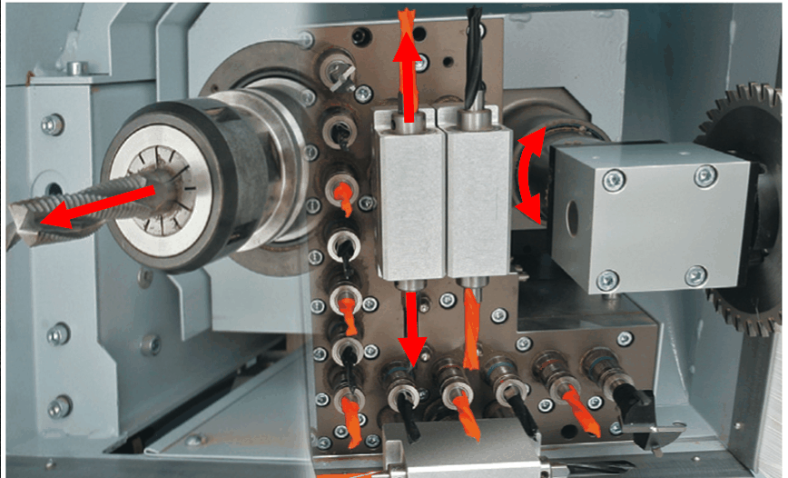
As you can see in the figure, machine spindles have a wide variety of different spatial orientations. Moreover, some spindles are capable of changing the tool spatial orientation before starting the working movement. When defining the spindle in the Woodwork for Inventor CAM environment, there is a requirement to indicate at what angle the spindle can be set up in space before commencing the operation. The sphere image is used to define the degrees of freedom of the spindle orientation. The degree of freedom of orientation is defined in two planes: horizontal and vertical.

Defining possible spindle rotation angles in the horizontal plane

Defining possible spindle rotation angles in the vertical plane

The result of defining the spindle axis spatial orientation in two planes
When defining the allowable minimum starting and maximum rotation end angle of spindle rotation in the horizontal plane, we define the angle sector in which the spindle axis can be set up in the given plane. In the horizontal plane, an allowable value for defining the start and end angle ranges from 0 to 360 degrees. Based on this, we can define the corner sector in the range from 0 to 360 degrees. The same can be done in the vertical plane. The only difference is that here the start and end sector angles are defined within the range from 0 to 180 degrees. The angle range is always taken from the start angle moving counterclockwise toward the end angle. In case the minimum and the maximum angles coincide, it is considered that the spindle’s position in this plane is fixed and it cannot change.
Note. The Woodwork for Inventor CAM system does not currently support design capabilities for 5D processing, i. e. during positioning, the tool can be oriented in space within the range of the defined degrees of freedom of the tool spatial orientation, but the tool cannot change its orientation and move along all three coordinates at the same time during a feed. In other words, it is an intermediate system between 2.5D and 5D processing which is usually known as slant manufacturing.
Below are the most popular cases of spindle specification
Fixed-direction vertical spindle.
Most common applications: vertical mills, drills.
Allowed spindle axis angle in XY plane:
| ▪ | Start Angle =0 deg |
| ▪ | End Angle = 0 deg |
Allowed spindle axis angle in ZX plane:
| ▪ | Start Angle =180 deg |
| ▪ | End Angle = 180 deg |
Fixed-direction horizontal spindle in +X direction.
Most common applications: horizontal drills, fixed-orientation vertical cutting saw blade in Y direction.
Allowed spindle axis angle in XY plane:
| ▪ | Start Angle =0 deg |
| ▪ | End Angle = 0 deg |
Allowed spindle axis angle in ZX plane:
| ▪ | Start Angle =90 deg |
| ▪ | End Angle = 90 deg |
Fixed-direction horizontal spindle in -X direction.
Most common applications: horizontal drills, fixed-orientation vertical cutting saw blade in Y direction.
Allowed spindle axis angle in XY plane:
| ▪ | Start Angle =180 deg |
| ▪ | End Angle = 180 deg |
Allowed spindle axis angle in ZX plane:
| ▪ | Start Angle =90 deg |
| ▪ | End Angle = 90 deg |
Fixed-direction horizontal spindle in +Y direction.
Most common applications: horizontal drills, fixed-orientation vertical cutting saw blade in X direction.
Allowed spindle axis angle in XY plane:
| ▪ | Start Angle =90 deg |
| ▪ | End Angle = 90 deg |
Allowed spindle axis angle in ZX plane:
| ▪ | Start Angle =90 deg |
| ▪ | End Angle = 90 deg |
Fixed-direction horizontal spindle in -Y direction.
Most common applications: horizontal drills, fixed-orientation vertical cutting saw blade in X direction.
Allowed spindle axis angle in XY plane:
| ▪ | Start Angle =270 deg |
| ▪ | End Angle = 270 deg |
Allowed spindle axis angle in ZX plane:
| ▪ | Start Angle =90 deg |
| ▪ | End Angle = 90 deg |
Spindle axis may be arranged at any angle in a horizontal plane.
Most common applications: saw unit with rotation around the Z axis, bevel cutting.
Allowed spindle axis angle in XY plane:
| ▪ | Start Angle =0 deg |
| ▪ | End Angle = 360 deg |
Allowed spindle axis angle in ZX plane:
| ▪ | Start Angle =90 deg |
| ▪ | End Angle = 90 deg |
Spindle axis may be arranged at any angle in a bottom semi-sphere segment.
Most common applications: drilling at any angle, milling of slanted contours or pockets, making slanted cuts.
Allowed spindle axis angle in XY plane:
| ▪ | Start Angle =0 deg |
| ▪ | End Angle = 360 deg |
Allowed spindle axis angle in ZX plane:
| ▪ | Start Angle =90 deg |
| ▪ | End Angle = 180 deg |