To open the Sizing by Mill command, go to:
Woodwork CAM -> Sizing->By Mill ![]()
In order for the command to run smoothly, the user has to follow a certain order of specifying the data. The description of the command control in the sequence to be followed when working with milling command window is described below.
| 1. | Update properties only for selected operation - Overwrite changed properties only for the current operation. |
| 2. | Update properties in all operations in current technology - Overwrite changed properties for all operations in the current technology. |
| 3. | Update properties for database - Overwrite changed properties in the database. |
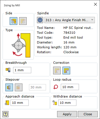
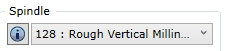
The command remembers the last spindle with the loaded tool. If during the next run of the command the same spindle with the tool is used, the user does not need to select it again.
In this operation, milling contour is calculated automatically and it is rectangular milling. The size of the rectangle is determined taking into account the calculated size of the workpiece, added oversize and the removable sizing allowance.
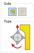
Positioning the tool, where the milled object is a part surface
Spindle rotation direction is constant and depends on the shape of the loaded milling tool. If the tool movement direction is changed, the movement direction for the milled contour is changed as well. Moreover, setting of the direction of the tool with respect to the processed contour also changes the milling method:
If the user does not select the movement direction of the tool with respect to the surface, the mill command automatically sets the movement direction so that climb milling is performed. This type of milling poses a lower risk of chipping a wooden part during milling. However, there are situations, where conventional milling is necessary. Therefore, the user may change the tool position with respect to the milled surface.
|


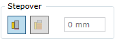
Switches layer-by-layer sizing contour milling on/off and allows the user to set the layer step.
If the layer-by-layer milling is on, the depth of one layer may be specified.
Important! The operation of this option is not represented in the graphical display of trajectory, but it has an impact when generating the final CNC programme.
|
When milling the sizing contour, the mill cuts through the body of the part. The user has to specify how much below the part depth the mill should be positioned. This value is set using the Breakthrough parameter.
|

When developing CNC programmes, the trajectory of the milling tool may be specified in the programme as the calculated movement of the centre of the tool or as a milled contour. Meanwhile, the tool radius is adjusted in the CNC machine itself. Each method has its own advantages and disadvantages. For example, tool adjustment function in machines is usually quite primitive and, faced with a complex contour, it is unable to process the situation or interprets it wrong. However, during design of CAM technology, tool dimension estimates are used. For example, the estimated diameter of the mill is 20 mm, and the actual diameter (after sharpening) may be 19.2 mm. Thus, reliance on CAM calculations may lead to problems with accuracy. On the other hand, accurate tool data is entered into machines. Therefore, if adjustment is made in the machine, the required accuracy is likely to be maintained. The user may choose the way of presenting the tool milling trajectory: as the tool centre trajectory or as the milled contour.
|
In order to achieve a clean and precise angle and ensure smoother movement of the tool during processing, corner bypass loop may be set at the corners of the contour. To do this, the user only needs to set the radius value greater than 0. If the radius value is equal to 0, a loop will not be generated in the corners.
|

Approach distance - The length of straight segment of the trajectory required for the tool to cut into the workpiece.
Withdrawal distance - The length of straight segment of the trajectory required for the tool to move away from the workpiece.
|