To open the pocket operation, go to:
Woodwork CAM -> Pocket ![]()
Once you open the command, a dialog window will appear.
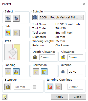
To successfully run the command, the user should follow a certain sequence for specifying data. Below you will find the description of the control of the command in the sequence that needs to be followed when performing tasks in the Pocket command window.
| 1. | Update properties only for selected operation. |
| 2. | Update properties in all operations in current technology. |
| 3. | Update properties for database. |
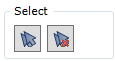
| 1. | Selection of individual surfaces. |
| 2. | Automatic selection of millable surfaces. |
| 3. | Clearing the set of surfaces. |
| 4. | A millable pocket contour expressed as closed-contour sketch geometry. |
Selection of individual elements
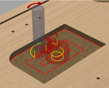
Surfaces that are suitable for the Woodwork for Inventor CAM Pocket operation are those surfaces of the part model that are flat and make up the bottom of the milled pocket. Also, this surface may be oriented in space in the manner as to ensure that the tool’s capabilities allow it to rotate it with its back facing this surface (see fig. below). A possible vector of the tool’s spatial orientation is specified when configuring the machine’s spindles.

The compliance of the normal vector of the pocket bottom to the tool’s direction vector
You can check if the surface can be included in the set by placing the cursor on the desired surface. Such a surface will be highlighted in white. The inclusion of the surface in the set is performed by selecting this surface with the mouse cursor. Once the surface has been included in the set, it is highlighted in blue. To remove a surface from the set, you need to select the surface while pressing and holding the "Ctr"l key.
![]() Automatic selection of surfaces
Automatic selection of surfaces
This option automatically selects pocket bottoms that can be processed with a given tool.
![]() Clearing the set of surfaces
Clearing the set of surfaces
Clears the current set of millable surfaces.
A millable contour expressed as sketch geometry
Sometimes there is a need to mill a pocket that is not directly expressed as a pocket bottom surface. For example, there exists machines with a vertical arrangement where a workpiece is mounted vertically. In such a machine, you cannot cut out a piece of the part that would separate from the workpiece because if such a piece drops down, it will damage the CNC machine. In this case, such a grove is milled as a pocket by shaving away all the inside material into shavings. Within the part model, such a pocket does not have a bottom and it is impossible to select it as reference geometry in the Pocket operation. In this case you need to draw a closed sketch and select it as reference geometry. Only one sketch can be selected for the mill operation. The plane of the sketch must meet the orientation capabilities of the spindle. The milling depth is set based on the sketch plane.

Turns on or off stepover contour milling and allows the user to set the stepover distance.
If the stepover is on, you can indicate the depth of one layer. Note. The functioning of this option is not visualized in the graphic view of the trajectory, but this option will have an impact on the generation of the final CNC program.
|

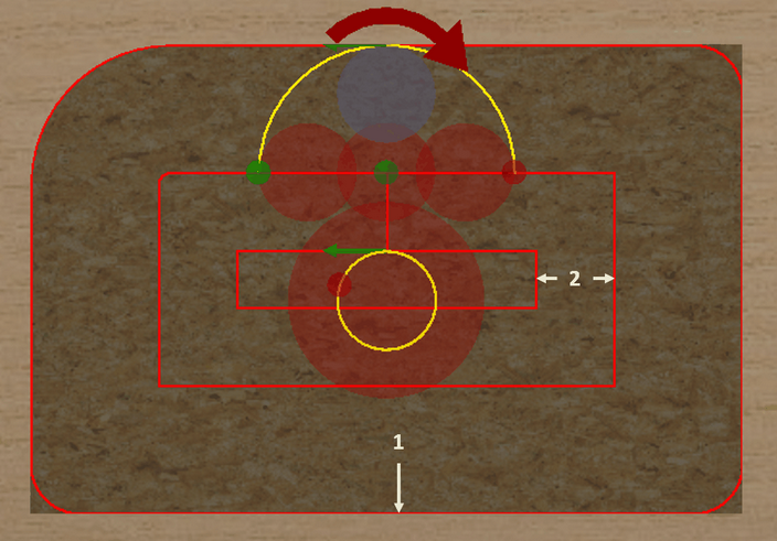
The meaning of this parameter is similar to that described in the contour Mill operation. However, there is one important thing to remember. During pocketing, two contours need to be distinguished which occur when calculating the tool trajectory (see fig. Below).
Two contours may be distinguished:
You should bear in mind that only the final contour is affected by the change of the correction type in the Pocket operation. The pocket inside removal contour is always calculated and generated as a contour with a tool correction which is calculated in the software.
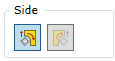
We have two options to select the correction type of the final contour:
|

Adjusts the size of the tool overlap when performing the pocketing passes. The value of this parameter is set in percentage from the tool diameter. The higher the percent, the more dense the pocketing trajectory is.
|

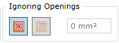
Disables the inclusion of holes on the surface of the pocket into the tool trajectory calculation.
|
A depth oversize allows the user to select how much material of the pocket needs to be left in terms of depth.
|

Allows the user to select an oversize with respect to the pocket contour. |