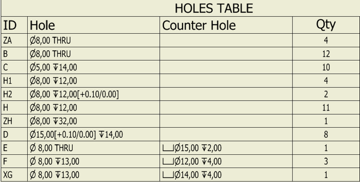
If the user does not have a holes table template in their drawing template, a table of the specified format is inserted in the drawing by default. However, various types of holes tables are required in the manufacturing process. The user of Woodwork for Inventor can create their own holes table template and use it when they need to set up a part drawing.
Holes table template is presented as a regular Autodesk Inventor general table. This table has to be inserted in the Woodwork for Inventor drawing template. The table includes several items that help Woodwork for Inventor to identify it as a holes table template.

The table must include at least:
| 1. | Holes header containing <HOLES-TABLE> keyword. The user can provide the desired table name next to the keyword. For example, Löcher Tisch<HOLES-TABLE>. When a drawing is generated, Löcher Tisch will appear in the header. |
| 2. | Next, the desired holes table columns are created in the table. |
| 3. | The first row is used for keywords according to which Woodwork for Inventor gathers the required information about holes and exports it to a table, when a drawing is generated. |
Woodwork for Inventor shape interpreter analyses the geometry of a part and collects information about all holes in the part. Then, it uses keywords from the holes table template to generate the appropriate holes table in the drawing. The operating principle of this interpreter is similar to that behind the output of holes notes. To create the contents of a note, combined keyword <HNOTE> is used (see the Holes notes section).
Currently, Woodwork for Inventor supports the following holes table keywords:
Hole Keywords |
Sense |
<HNAME> |
Hole Index name |
<HTYPE> |
Hole type |
<HSIDE> |
Hole side |
Hole definition Keywords |
|
<HDIA> |
Hole diameter |
<HDIATOL> |
Hole diameter tolerance |
<HDPT> |
Hole depth |
<HDPTTOL> |
Hole depth tolerance |
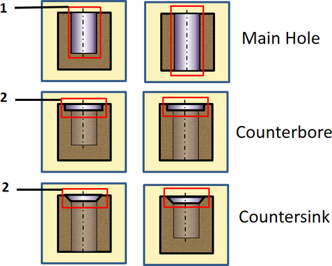
Counter Bore definition Keywords |
|
<CBDIA> |
Counterbore diameter |
<CBDIATOL> |
Counterbore diameter tolerance |
<CBDPT> |
Counterbore depth |
<CBDPTTOL> |
Counterbore depth tolerance |
Counter Sink definition Keywords |
|
<CSDIA> |
Countersink diameter |
<CSDIATOL> |
Countersink diameter tolerance |
<CSANG> |
Countersink angle |
<CSANGTOL> |
Countersink angle tolerance |
<CSDPT> |
Countersink depth |
Generalized Counter form of Hole definition Keywords |
|
<CDIA> |
Counter (bore and sink) diameter |
<CDPT> |
Counter (sink or bore) depth |
Positioning and orientation Keywords |
|
<XDIM> |
X coordinate |
<YDIM> |
Y coordinate |
<ZDIM> |
Z coordinate |
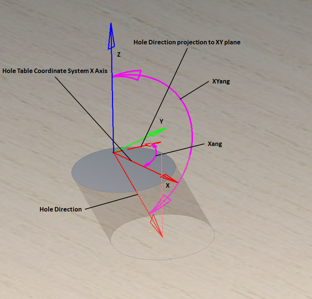
<ATOX> |
Angle to x axis |
<ATOP> |
Angle to plane |
Quantity Keywords |
|
<QTY> |
Quantity |
<QTYNOTE> |
Hole note quantity |
Hole annotation additional fields Keywords |
|
<ADDFIELD1> |
The additional field1 |
<ADDFIELD2> |
The additional field2 |
<ADDFIELD3> |
The additional field3 |
<ADDFIELD4> |
The additional field4 |
<ADDFIELD5> |
The additional field5 |
Consolidated Keywords |
|
<HNOTE> |
Hole note |
<MHDESC> |
Main hole description |
<CHDESC> |
Counter hole description |
Information about the position of a hole in a part can be exported to a holes table.
The following keywords are used to export hole coordinates:
The exported coordinates depend on the reference point specified when configuring settings for the export of a holes table to a drawing. To read more, click here.
The following keywords define the orientation of holes:
|
All keywords used in holes tables are roughly classified into regular and combined keywords. Regular keywords retrieve hole information and export it to the table or a combined keyword. While combined keywords are used in cases where merged information retrieved by several keywords has to be exported to a column and information about different hole types has to be exported to the same column.
For example, we want to export merged information about the hole diameter, diameter tolerance and depth "n8.0[+0.1/-0.1]x12.00". As you can see from the example, the keyword includes diameter, depth and tolerance values and special characters. Such keyword has to be used due to different rules of hole description applied by different companies, hole type, etc. To meet such requirements, combined keywords are used. Such keywords can include special characters, several other keywords. When such keywords are used in a table or hole note, information retrieved by several keywords is merged and presented as a single entry.
Composite holes can be roughly classified into:
Woodwork for Inventor offers the possibility to configure these keywords according to your needs. This is done by combining the above regular keywords and text into a single combined keyword template. Such combined keyword template is created for each hole type. When Auto Plot command is started, holes interpreter recognizes the hole type and applies the appropriate combined hole template accordingly. If such template is already included in the holes table template, hole parameters are exported to the table or hole note within the drawing.
 Diagram – keywords that may be included in combined keywords
For more information about creating combined keywords, click here. |