To open the Groove command, go to:
Woodwork CAM -> Groove 
Once you open this command, a dialog window will appear.
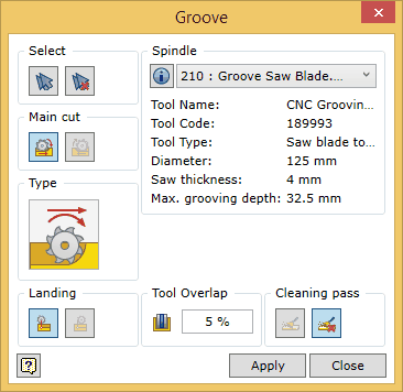
To successfully run the command, the user should follow a certain sequence for specifying data. Below you will find the description of the control of the command in the sequence that needs to be followed when performing tasks in the Groove command window.

 . A window for editing spindle data will appear. In this window you can also edit all data related to cutting modes (cutting feedrate, rotation speed of the spindle, etc.). The data changes can be saved in the following ways: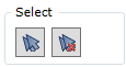
| 1. | Selection of individual groove bottom surfaces. |
| 2. | Automatic selection of groove bottom surfaces. |
| 3. | Clearing the set of surfaces. |
| 4. | A groove bottom surface expressed as a flat Autodesk Inventor surface. |
Selection of individual elements
Surfaces that are suitable for the Woodwork for Inventor CAM Groove operation are those surfaces of the part model that are flat and bounded by an edge extending on at least one side and that are not narrower than the width of the saw blade. Also, these surfaces must meet the possible saw blade axis orientation in space (see fig. below). A possible vector of the tool’s spatial orientation is specified when configuring the machine’s spindles.
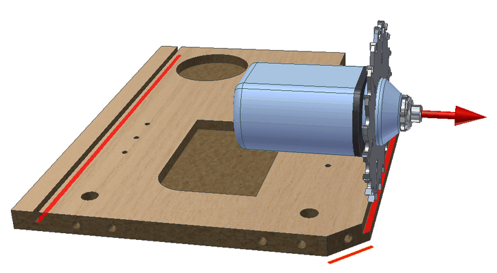
You can check if the surface can be included in the set by placing the cursor on the desired surface. Such a surface will be highlighted in white. The inclusion of the surface in the set is performed by selecting this surface with the mouse cursor. Once the surface has been included in the set, it is highlighted in blue. To remove a surface from the set, you need to select the surface while pressing and holding the "Ctrl" key.
 Automatic selection of surfaces
This option automatically selects pocket bottoms that can be processed with a given tool.
 Clearing the set of surfaces
Clearing the current set of millable surfaces.
Groove bottom expressed as an Inventor flat surface
Sometimes there is a need to mill a groove or to perform a cut that is not directly expressed as a groove bottom surface of the part body. In this case, you can draw a line sketch and stretch it as a surface. In this way we will obtain geometry which can be selected as a groove bottom for the groove operation.


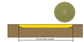
When landing the saw blade for grooving and when withdrawing the blade from the groove, the following two options are available:
Note. If the groove has an open end in the model, the command will not respond to these options at that end. At this type of the groove end, the saw blade will be used in the way as if applying the landing/withdrawal option preventing the depth of groove.
|

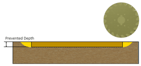

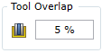
If the groove to be cut is wider than the width of the saw blade, an additional blade pass will be required. For this pass, you need to indicate the overlap value for the saw blade toolpath. The overlap is specified in percent from the thickness of the blade. The change of this value is not reflected in visualizing the tool trajectory in the graphic view. This, however, will have an impact on the generation of the CNC program.
|
You may turn on/turn off the saw blade cleaning pass to clean the groove. If the pass is on, the saw blade will travel along the groove again rotating around its axis and cleaning the shavings from the groove, at a small distance above the groove bottom. The change of this value is not reflected in visualizing the tool trajectory in the graphic view. This, however, will have an impact on the generation of the CNC program. |