As mention in the section about the calculation of part and workpiece size, two factors have direct impact on the size of workpiece used to produce a constructed part of furniture. These are grain direction of the material and additional oversize assigned by the user for performance of one or the other operation. Woodwork for Inventor has a command that allows the user to control these factors.
To open the command, go to:
Woodwork Design –> Material –> Grain ![]()
In this case, the command is activated using an active grain control TAB.

or
Woodwork Design –> Material –> Workpiece Oversize ![]()
In this case, the command is activated using an active oversize control TAB.
In any case, the active tab can be changed and grain adjustment and oversize assignment tasks may be performed without closing the command.
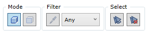
At the top of the command dialogue, there is a zone for managing the creation of component sets. The term “Component” used in the description means a part or part surface, which is coated with some cover. The type of components you work with depends on the selection mode the command is working in (see the description below). These component sets will be subject to operations provided for by the command.
|
Concept
Grain direction can be controlled from Grain control TAB. Grain direction may be controlled for multiple selected components. In order to understand the control of grain direction, the user should be aware of several concepts and how they affect the mechanism of changing grain direction.
Imaginary crossing plane. The imaginary crossing plane is created by drawing it through the grain direction indicator vector X and the indicator coordinate system axis Z. This plane is intersected with the reference face of the component, which results in an intersection line. The direction of this line shows the grain direction of a particular component.
Grain direction indicator coordinate system. Grain indicator may be present on several coordinate systems:
Screen coordinate system
 Grain direction indicator screen coordinate system
Grain direction indicator screen in arranged on the screen plane. Its axis X lies on the plane and is horizontal and axis Y also lies on the plane, but is vertical. Component grain direction is found according to the intersection line between the imaginary crossing plane with the reference face of the selected component (see figure above). Rotating the grain direction indicator changes the position of the imaginary plane and calculates different possible grain directions of the selected component. The command provides several mechanisms to rotate the grain direction indicator. As shown in the figure above, grain direction depends on the orientation of selected components in respect to the screen and the angle of rotation of the indicator in respect to the horizontal axis. By default, when working in assembly, screen coordinate system is automatically selected for determining the grain direction.
Coordinate system defined by component grain direction vector
 Component grain direction coordinate system
Coordinate system defined by component grain direction is aligned according to the grain direction of the specific selected component. In this case, the grain direction is determined by the position of grain direction of the selected component. Just like in the coordinate system described above, the imaginary crossing plane is calculated using the indicator and indicator coordinate system axis Z. Grain direction for each component is determined according to the intersection line between the imaginary crossing plane and the reference face of the component.
Important! For components, where reference faces are parallel to the imaginary crossing plane of grain control indicator, the intersection is not possible. In such case, grain direction cannot be changed.
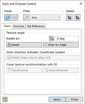
Grain control TAB
|
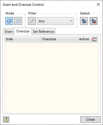
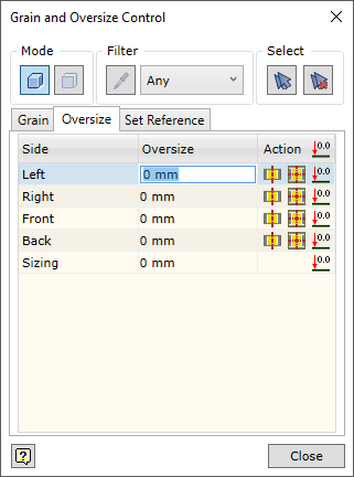
Oversize can be controlled in Oversize TAB.
|
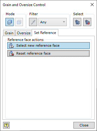
Reference face of the part determines which side of the part will be considered top or bottom side. Their grain direction is used to calculate the size of the part, etc. During the initial assigning of material, the reference face is determined automatically. However, the constructor may for various reasons be not satisfied with the selection of reference face. The user can change the reference face of the part using Set Reference TAB.
|
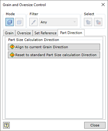
When a Woodwork for Inventor material is assigned to an Autodesk Inventor part, the grain direction is set automatically. Part size is calculated using this initial direction. As the user changes the grain direction, the calculation of the workpiece size also changes. The direction of the part size calculation remains the same. In most cases, this is acceptable for the assembly process. However, in exceptional cases, where the part size calculated based on the automatically set direction vector is not acceptable, the direction of size calculation can be changed. The part sizes exported to BOM are changed accordingly. This can be done using the Part Direction tab. The tab is activated by opening the part file separately
Before setting the part size calculation direction, rotate the grain direction as desired. Choose one of the following options.
|