Providing drawings for production is the main result of the furniture constructor’s work. The Woodwork for Inventor add-on has an automatic drawing preparation module (AutoPlot). This module allows the user to automatically generate drawing bundles for the entire furniture product. Using the options provided by the module, you can configure the structure and appearance of the output documentation and create technical documentation sets that would meet your business requirements for issued documents.
Auto Plot templates. The drawing bundle generated by this command is created based on the pre-designed templates. A template is an Autodesk Inventor drawing file (*.idw) which contain information indicating how the AutoPlot command should work. When starting the AutoPlot of the drawing bundle, the user specifies the template based on which the formatting of this bundle is performed. Woodwork for Inventor has several templates which can be modified by the user at his own discretion, adapting it to individual business needs.
During template configuration, the user may adjust the following AutoPlot aspects:
| 1. | View composition in the sheet. |
| 2. | Number of component views; its orientation in different views; visualization style and scale. |
| 3. | Exports Woodwork for Inventor specifications in the form of tables on the drawing sheet. |
| 4. | Various aspects of the export of information generated by Woodwork for Inventor to a drawing, for example, edge marking, range box placement. |
| 5. | Output of hole information to a drawing in which the content of the holes table and its visualization aspects, automatic hole dimensioning, etc. are configured. |
| 6. | Linking own symbols to Woodwork for Inventor information such as grain direction marking, base point placement, etc. |
| 7. | Configuration of the generated drawing bundle which defines the composition of the bundle. |
| 8. | Options of automatic export of a drawing to other formats. |
AutoPlot drawing bundles. Depending on specific business requirements in place, a variety of document bundles need to be produced. For example, you may need to print a set of labels for each part or to have a separate file for production where an assembly is printed on one sheet, whereas on other sheets, components constituting an assembly are printed. Woodwork for Inventor offers six types of such bundles. In a template, the user can indicate what document bundle needs to be generated. During the printing process, the assembly being printed is analyzed and its components are arranged based on the drawing bundle rules contained in the template. Click here for a description of components that can be created using Woodwork for Inventor.
Woodwork for Inventor has several pre-designed templates which you can modify at your own discretion and adapt them to your business needs. After completing the add-on installation, you will find these templates at the following location on your computer:
C:\Users\Public\Documents\Woodwork for Inventor\2023\v13\Auto Plot templates
Label creation and modification. Another important aspect of the AutoPlot is outputting Woodwork for Inventor information to drawings. When using the Woodwork for Inventor add-on, the parts of the model are assigned with a lot of different information, e. g. material information, part edge banding information, part size information, etc. It is useful to see this information in drawings.
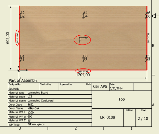
The figure above depicts a fragment of the drawing which contains information about edge banding, grain direction, and a part in a title block. Woodwork for Inventor has different types of labels intended to define information created while using Woodwork for Inventor in a drawing. The user has an opportunity to create a specific symbol for each such label which is placed in a required position in the drawing during AutoPlott process. The user can include a Prompted Entry into the symbol’s structure. This symbol entry is interpreted during the drawing generation process: relevant information is read from the component model and its meaning is output to the label symbol being inserted. For example, the user can create a symbol for designating an edge band containing information about the edge band color and thickness. Symbols are stored in the Autodesk Inventor (*.idw) file which serves as a symbol container. During label configuration, you can select a desired symbol for each label type from the container file and in this way link it to the label type. Click here for a description of label types that are used by default in Woodwork for Inventor.
Woodwork for Inventor has a symbol container located at:
C:\Users\Public\Documents\Woodwork for Inventor\2023\v13\Auto Plot templates\Symbols.idw.
These symbols are used in the provided Woodwork for Inventor Auto Plot templates. The user, at his own discretion, may create a new symbol file or modify the content of a provided file and create own symbols which are needed to select Woodwork for Inventor elements in a drawing.
Material replacement interpretation. As you have already learn from the previous descriptions, Woodwork for Inventor recommends working with summarized materials, whereas specific materials to be used in production can be assigned during replacement configuration. The AutoPlot command allows the user to specify replacement configuration based on which information fields about a given material will be filled in the drawing. In this way, information generated in BOMs will be linked to the information in the drawings.