Generating the structure of a part

Top | Previous | Next


When assigning materials, the model of the part does not undergo any geometrical modifications in the Woodwork for Inventor environment. The assigned cover materials (which affect the calculation of dimensions of the workpiece and the part) are taken into account when generating BOM reports. However, there are certain construction situations, where it is essential for the user to see or show the cover solid in relation to the actual workpiece solid in a technical drawing. This is a common case when it comes to edge banding. Showing the structure of a multilayer material workpiece can also be important. Woodwork for Inventor has a command which, according to assigned materials, automatically creates a separate representation of the part out of solids, which accurately represents the composition of the part. This way, the user can clearly see the structure of the part. This command replaces the Edge Band Wizard command from the previous version of Woodwork for Inventor.


hmtoggle_plus1Generating the structure of the part


Opening the command


Woodwork Design –> Material –> Build Structure Build Structure of Part


Build Part Structure Command


Or, if the command is running, it can be accessed from Assembly


Build Part structure Command from assembly


Select single entity

Select single part

It allows specifying individual parts in an assembly, for which the part structure has to be generated.


32x32 Assign Material


All Woodwork Parts

All parts with Woodwork for Inventor materials are included in the set.

Build Structure of Part

Build

Generates workpiece structure for selected parts, expressing it as individual solids. Each solid is named according to the type of material of the workpiece it represents. This way, a solid representing the edge band will be named “Edge Band <n>”, a solid representing the veneer will be named “Veneer <n>”, etc. Two View Representations are automatically generated:


1.Monolithic, representing the original solid of the part. This solid is the essential piece of information when working with Woodwork for Inventor. All calculations required for generating BOM reports, CAM technologies, etc. are based on this information.


2.Structural: structural representation of the composition of the part. It can be used at the user’s discretion, including when generating drawings. However, bear in mind that the generated representation is not associative. If the dimensions of the part are changed, the structure has to be generated again using the same Build Structure command or the Refresh command. This is why the drawing should be generated at the last stage of work, when the construction of the part does not change any more, because all notes of the drawing lose their reference during re-generation.


Delete Built part structure

Remove


Removes the generated structure of workpieces, leaving only the monolithic structure of the part.


hmtoggle_plus1Workpiece queuing


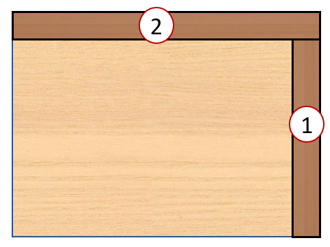
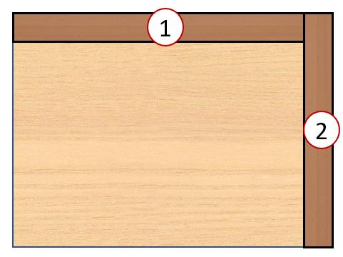
The shape of solids of automatically generated cover workpieces depends on the order of placing the covers on the part.


The top edge is second in queue, so it overlays the side edge.

The top edge is second in queue, so it overlays the side edge.

The top edge is second in queue, so the side edge overlays the top edge.

The top edge is second in queue, so the side edge overlays the top edge.


As shown in the figure above, the order in the queue determines which cover workpiece overlays the other. The queue of covers is set by the user, i.e. the order is the same as the order of assigning cover materials when using the Material assignment command. However, the user may not be satisfied with this queue and there is an additional tool to change the order in the queue: Covering Queue. This command is accessible only in edit mode.


Opening the command


Woodwork Design –> Material –> Covering Queue Covering Queue


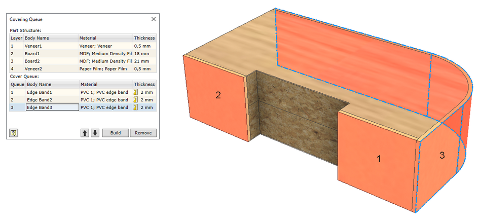
Cover Queue dialog


The dialogue is divided into two zones:


Part Structure

This zone displays the layers of a multilayer material. It is for information purposes only. The order of layers cannot be changed here. It can be changed only by editing the composition of the multilayer material using the Material Editor command or by creating a new material using the Material assignment command.

Cover Queue

This zone shows cover workpieces and their order can be changed by shifting the position of the item in the queue of covers. The place of the item in the queue is also represented in the model. The workpiece may be selected both in the dialogue window and the graphical model of the part.

Build

Creates or re-generates workpiece solids.

Remove

Removes the structural representation of the part.