This command can be used to create a panel body based on the face of the skeleton or its section in terms of the working plane.
Opening the Command
The command can be opened only in the part design environment.
Skeleton Dress Up –> Dress Up ![]()
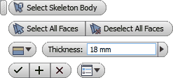
Select Skeleton Body - first, the command will ask you to select the skeleton body, for which panel bodies are to be created. If a solid body is selected, it will be automatically turned into a skeleton body.
Choose the skeleton body first. Then, the command will wait for the user to create a set of geometry elements so that, based on these, panel bodies could be created. The set can be created as follows:
| 1. | Use the cursor to select individual faces of the skeleton or working planes intersecting the skeleton. Hold "Ctrl" key to eliminate unwanted elements from the set. |
| 2. | Select All Faces - automatically selects all faces of the skeleton. |
| 3. | Deselect All Faces - deletes the content of the created set; new set can now be created. |
As mentioned above, at this point, reference geometry element can be created from a face of the skeleton body or working plane intersecting such body. Panel body will be created based on the edge of the face or the resulting section loop.
Once the set of reference geometry elements has been created, it is necessary to define the position of the panel with regard to the selected element. The following options are available here:
1. ![]() – the panel will be created turned from the selected face towards the inside of the skeleton body. In case of section of the working plane, the panel body will be created in a negative direction with regard to the normal of the plane.
– the panel will be created turned from the selected face towards the inside of the skeleton body. In case of section of the working plane, the panel body will be created in a negative direction with regard to the normal of the plane.
2. ![]() – the panel will be created turned from the selected face towards outside of the skeleton body. In case of section of the working plane, the panel body will be created in a positive direction with regard to the normal of the plane.
– the panel will be created turned from the selected face towards outside of the skeleton body. In case of section of the working plane, the panel body will be created in a positive direction with regard to the normal of the plane.
3. ![]() – the panel will be created with the selected face running along its centre. In case of section of the working plane, the panel body will be created with the face of the working plane running along its centre.
– the panel will be created with the selected face running along its centre. In case of section of the working plane, the panel body will be created with the face of the working plane running along its centre.
Once the set has been created, each selected element will be marked with a direction indicator.
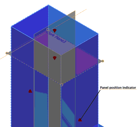
Panel body position can be individually specified for each plane. To do this, point the cursor at the position indicator.
Thickness - thickness of the created panel is specified in the field.
Apply - confirms all the selected items and creates panel bodies. The command remains active and new items can be selected as well as other panel bodies can be created.
OK - confirms all the selected items and creates panel bodies. The command is then closed.
Cancel - canceling the command.
Important. When creating a panel, the panel body is automatically assigned a name comprised of a prefix and base. The prefix consists of the skeleton body name and the base consists of the word Panel and a serial number. For example, skeleton body name is Wardrobe, so all panels created based on this body will be named as follows:
Wardrobe Panel 1
Wardrobe Panel 2
...
Wardrobe Panel n
Once the skeleton bodies are properly renamed, it will be easier to navigate among all panel bodies.