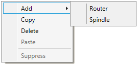
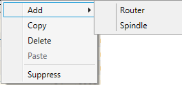
As mentioned earlier, the spindle data container may be created through a context menu in one of the following two ways:
| ▪ | By copying (Copy): spindle data is copied to the buffer, and using the Paste feature a spindle copy may be created in the same CNC machine. Or you can place the cursor on another machine and the copy will be respectively placed in another machine.
|
| ▪ | By creating a new spindle: a new "empty" spindle will be created which will be automatically included in the Tool-less group. Once such a spindle is set up with a tool, it is automatically removed from the above group (Tool-less) and transferred to a relevant spindle group. |
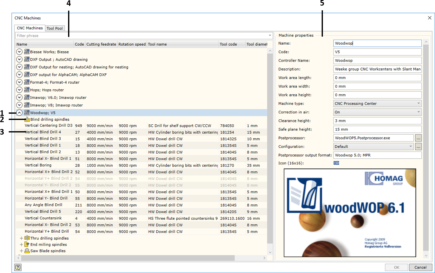
To edit spindle data, you need to place the cursor on the spindle data node on the left hand side of the window. Then a tab will appear on the right hand side of the window displaying the data of a given spindle. The spindle data tab will differ depending on the tool that has been setup in the spindle. When changing the tool, the spindle group will be automatically changed along with the data fields describing the spindle.
Below you will find the description of the data editor window for each group.
 Data tab of Through Drills and Data tab of Through Drills and  Blind Drills group spindle Blind Drills group spindle

Name
|
Spindle name
|
Code
|
Spindle code, number. In the CNC program, this code usually appears as a tool identification code. For instance, T01, T10, etc.
|
Cutting feedrate
|
Is the speed at which the cutter moves with respect to the work material. It is expressed in mm/min in metric units, and inch/min in imperial units.
|
Rotation speed
|
The rotation speed of the spindle. It is expressed in revs/min.
|
Tool specifying
|
Tool specification method in the CNC program being generated. Possible values:
Click here for more information about the values of the above parameters.
|
Tool withdrawal feedrate
|
The speed at which the tool is withdrawn from the drilled hole. Some systems require this parameter.
|
Tool
|
Tool selection drop-down list (see fig. below). This list contains all the items of the Tool Pool which are grouped by tool type. If you select an item using the cursor and click the "Select Tool" button, the selected tool will be setup in the spindle being edited. Remember that the changing of the tool also changes the spindle group by which the tool type belongs.
|
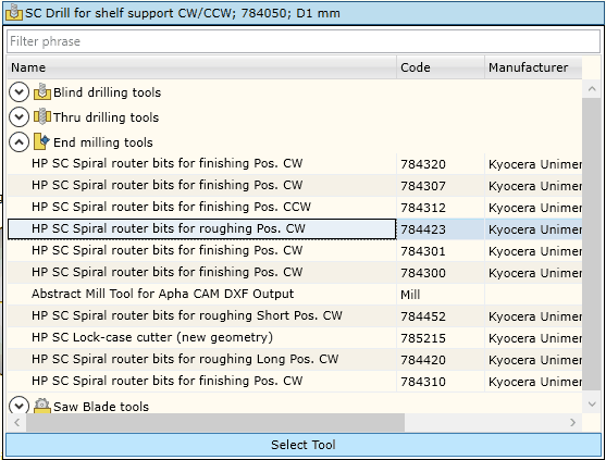
The data of the tool selected in this window that cannot be edited are displayed below in grey.
 End Mill group spindle tab End Mill group spindle tab
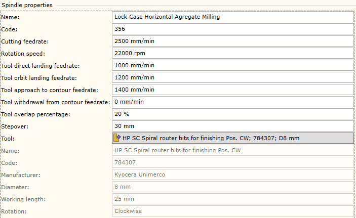
Name
|
Spindle name.
|
Code
|
Spindle code, number. In the CNC program, this code usually appears as a tool identification code. For instance, T01, T10, etc.
|
Cutting feedrate
|
The speed at which the cutter moves with respect to the work material. It is expressed in mm/min in metric units, and inch/min in imperial units.
|
Rotation speed
|
The rotation speed of the spindle. It is expressed in revs/min.
|
Tool direct landing feedrate
|
Feedrate of the vertical landing of the tool to the material.
|
Tool Orbit landing feedrate
|
Feedrate of the orbit landing of the tool to the material.
|
Tool approach to contour feedrate
|
Feedrate at which the tool approaches to the contour.
|
Tool withdrawal from contour feedrate
|
Feedrate at which the tool withdraws from the contour.
|
Tool overlap percentage
|
The percent of the tool overlap based on the diameter in the Pocket operation. When creating an operation, this parameter is provided as a default parameter. You can change this parameter when creating an operation.
|
Stepover
|
Stepover distance in the Mill or Pocket operation. When creating an operation, this parameter is provided as a default parameter. You can change this parameter when creating an operation.
|
Tool
|
Tool selection drop-down list. This list contains all the items of the Tool Pool which are grouped by tool type. If you select an item using the cursor and click the "Select Tool" button, the given tool will be setup in the spindle being edited. Remember that the changing of the tool also changes the belonging of the spindle to the group by tool type.
|
 Saw Blades group spindle tab Saw Blades group spindle tab

Name
|
Spindle name.
|
Code
|
Spindle code, number. In the CNC program, this code usually appears as a tool identification code. For instance, T01, T10, etc.
|
Cutting feedrate
|
The speed at which the cutter moves with respect to the work material. It is expressed in mm/min in metric units, and inch/min in imperial units.
|
Rotation speed
|
The rotation speed of the spindle. It is expressed in revs/min.
|
Tool overlap percentage
|
The percent of the tool overlap based on the width of the saw blade in the Groove operation. When creating an operation, this parameter is provided as a default parameter. You can change this parameter when creating an operation.
|
Tool
|
Tool selection drop-down list. This list contains all the items of the Tool Pool which are grouped by tool type. If you select an item using the cursor and click the "Select Tool" button, the given tool will be setup in the spindle being edited. Remember that the changing of the tool also changes the belonging of the spindle to the group by tool type.
|
|