The command performs the arrangement of joints or other standard components in the assembly model. It is performed based on the iMate arrangement constraints pre-written in the component. The component is arranged based on the relevant geometry in the assembly model consistently specified for each assembly constraint. This command has a several default modes:
| ▪ | Single – where one geometric element is specified for one constraint in the model. An example can be a plane on which an axis is arranged: in this case, a component arranged to implement a constraint immediately changes its spatial position. |
| ▪ | Multiple – where several geometric elements are specified for one constraint in the model. In this way, for the arranged component you may specify that its axis should be arranged based on several spatial planes. Then the command allows specifying a required geometry in the model for each assembly constraint, and inserting a new unit of the component being arranged in each available constraint realization position. |
To open the command, go to:
Woodwork Design –> Joint –> Attach ![]()
|
On-screen selection of a joint component inserted in the assembly. |
|
Joint component selection from the specified catalogue on the disk. If an iPart component is selected, the component configuration window is opened and the user can select the required configuration of the inserted component. If an iPart component with a custom parameter is being inserted, the user can specify the member name and location on the disc.
 iPart Component configuration window
 iPart Component with Custom Parameter configuration window
|
|
The use of the component last used in the command for performing the next arrangement. One of the five last inserted components can be selected from the dropdown list.
|
|
Enabling the single arrangement mode.
|
|
Enabling the multiple arrangement mode.
|
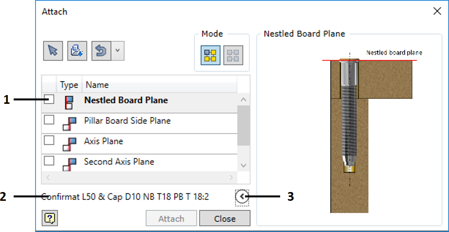
1. |
A space where the iMate assembly constraints of the selected component are represented. Unchecked the box means cancellation of the selected assembly constraints and re-enabling selection of the specified constraint.
|
2. |
Part Number of the component selected for insertion.
|
3. |
Collapsing additional window displaying images that illustrate component insertion. The window presents images that illustrate component insertion. Registration of such images for a component is described below. |
|
If an iAssembly or assembly component is inserted, the dialogue displays a check box that allows assigning the flexible assembly status to such component. |
The command is executed by clicking the "Attach" button.
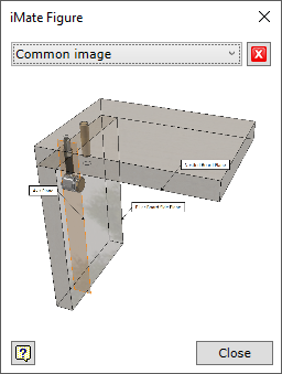
In order for the inserted component to display illustrations explaining the operation and application of iMate arrangement constraint during the dialogue, such illustrating images have to be registered for the given component. If it is an iPart or an iAssembly, registration has to be performed while editing the images for their Factories.
A command is used to perform this
Manage –> Author –> iMate Figure
Important! Registration of an image means that the component is being edited. Therefore, the component must be placed in the workspace of the current Autodesk Inventor project. |