Accessed via the menu: Components output to drawing -> Part -> Holes -> Table configuration -> Hole Table placement
This sub-menu item is used to position a holes table in a drawing.
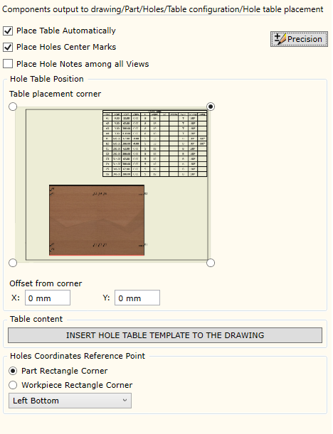
| ▪ | Place Hole Automatically: orders automatic generation of a holes table and its placement in a drawing. |
| ▪ | Place Holes Center Marks: orders automatic marking of hole centers when creating a table. |
| ▪ | Place Hole Notes among all Views: orders indexing of holes in several drawing views, if these were ordered (see section on the indexing of holes). |
| ▪ | Hole Table Position: specifies a corner on the panel to which the table will be attached. |
| ✓ | Offset from corner: possibility to order additional offsetting of a table from the specified corner. |
This table has three rows:
The table can be edited using Autodesk Inventor tools. You can add or delete columns, modify the content of the exported information to obtain the desired table form. |

Reference Point of holes coordinates: panel used to specify the reference point position. The panel is used to calculate hole coordinates with respect to the displayed part. Available options:
| ▪ | Part surrounding rectangle corner: the specified point is in one of the corners of the rectangle surrounding the part. |
| ▪ | Workpiece surrounding rectangle corner: the specified point is in one of the corners of the rectangle surrounding the workpiece. |
In the dropdown list, you can select the specific corner of the rectangle in which the basic reference point will be positioned.