Accessed via the menu: Components output to drawing -> Assembly
This section presents a description of all options necessary for assembly visualisation in a drawing.
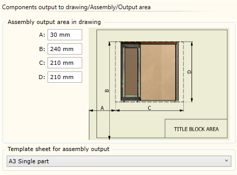
| ▪ | Assembly output area in drawing panel defines the drawing area used for the output of the generated assembly views. |
| ▪ | Template sheet for assembly output panel has a dropdown menu used to select a template sheet that will be used to generate a drawing of an assembly. |
|
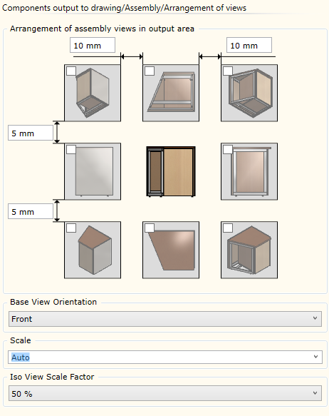
| ▪ | Arrangement of assembly views in output area panel is used to specify the views to be used for the visualisation of an assembly in a drawing. Holding the cursor on the view box for a while will open view color options: |

|
Wireframe representation.
|
Wireframe representation with hidden lines.
|
Rendered view with the colors of the piece of furniture.
|
| ▪ | Base View Orientation: allows specifying the orientation of an assembly in the centre view. The orientation is defined in relation to a View Cube. |
| ▪ | Scale allows choosing the scale of the assembly view. Auto option always recalculates view scales so that the view fits into an output area. Otherwise, when the selected scale is specified, only the start point coordinates of the output area from the output area settings are used. In this case, the area size is not taken into account. |
| ▪ | Iso View Scale Factor: allows specifying the scale factor for an isometric view. Scale factor is taken from the base view scale. |
|