To open the Mill command, go to:
Woodwork CAM -> Mill ![]()
A dialog window will appear once you open the command.
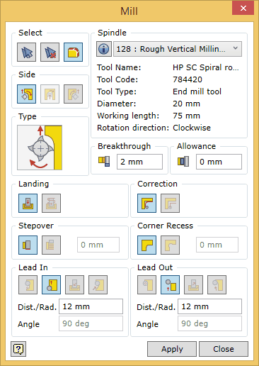
To successfully run the command, the user should follow a certain sequence for specifying data. Below you will find the description of the control of the command in the sequence that needs to be followed when performing tasks in the mill command window.

| 1. | Update properties only for selected operation. |
| 2. | Update properties in all operations in current technology. |
| 3. | Update properties for database. |
The command remembers the last selected spindle and the tool installed in it. If the same spindle and the tool can be used during the next execution of the command, there is no need to select the required spindle again.
![]() Selecting geometry in the mill command
Selecting geometry in the mill command
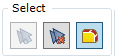
| 1. | Selection of individual surfaces. |
| 2. | Automatic selection of mill-able surfaces. |
| 3. | Clearing the set of surfaces. |
4. Selection of tangentially connected surfaces.
5. A mill-able contour expressed as sketch geometry.
We will briefly describe the above options.
Selection of individual surfaces
Surfaces that are suitable for the Woodwork for Inventor CAM milling operation are those surfaces of the part model that are curved only in one direction and the radius of curvature of this surface lies in the normal plane for the possible direction vector of the tool (see fig. below). A possible vector of the tool’s spatial orientation is specified when configuring the machine’s spindles.
You can check if the surface can be included in the set by placing the cursor on the desired surface. Such a surface will be highlighted in white. The inclusion of the surface in the set is performed by selecting this surface with the mouse cursor. Once the surface has been included in the set, it is highlighted in blue. To remove a surface from the set, you need to select the surface while pressing and holding the Ctrl key.
![]() Automatic selection of surfaces
Automatic selection of surfaces
This selection automatically creates a set of surfaces which can be processed with a given tool. There are several features you need to know before using this function.
| 1. | Automatic selection of surfaces is active in the command if the selected spindle has a fixed orientation in space, i. e. the way it is defined does not allow rotating it to a different direction. In this case the system analyzes the part model in the given direction of the spindle axis and selects millable contours. The system will automatically select all contours that cross the part. |
Surfaces that end with a pocket bottom are not automatically included in the set of millable surfaces. Also, if the machine is a CNC processing centre type and if the processed part workpiece does not have oversize from this side, it is interpreted that the external contour of the part, obtained in cutting the raw material board, does not require additional processing. For this reason, the straight side surfaces of the part are not included in the automatically created set of millable surfaces.
However, such surfaces can be additionally included in the set by selecting them as individual elements. Also, you can remove an individual surface from the automatically created set of surfaces by selecting the surface while pressing and holding the Ctrl key. In this way any surfaces that meet the processability criteria can be additionally included or removed from the automatically created set of surfaces.

1. A set of surfaces automatically created for a vertical spindle
2. The surface was not included in the set because it is bounded by a bottom.
| 2. | In case the spindle can change its orientation in space (the spindle head with 5D processing capabilities), the automatic surface selection button will be inactive after starting the command for creating the mill operation. This happens because the part shape analyzer does not know which direction to take to search for the millable surfaces. If the user specifies one curved surface or several intersecting flat surfaces, the spindle axis vector required for processing these surfaces will be set and the automatic selection function will become active. After using this function, all surfaces that meet the specified spindle axis vector are automatically selected. To process the surfaces using the same tool in a different direction, you need to re-start the command for creating a mill operation and to create a new set of surfaces. |
![]() Clearing the set of surfaces
Clearing the set of surfaces
Clearing the current set of millable surfaces.
![]() Selection of tangentially connected surfaces
Selection of tangentially connected surfaces
When performing the selection of individual surfaces, it is convenient to collectively include the tangentially connected surfaces into the set in one step. To do this, you can use the selection option allowing you to control the selection mode. The following options are available:
![]() Tangent surface selection mode: Allows the user to select one of the tangentially connected surfaces and include all the tangentially connected surfaces into the set.
Tangent surface selection mode: Allows the user to select one of the tangentially connected surfaces and include all the tangentially connected surfaces into the set.
![]() Single surface selection mode: Allows the user to select surfaces one by one.
Single surface selection mode: Allows the user to select surfaces one by one.
A millable contour expressed as sketch geometry
Sometimes there is a need to mill a contour that is not directly expressed as a part surface. In this case, there is an option allowing the user to select the millable contour as a sketch drawn by the user. Only one sketch can be selected for the milling operation. The plane of the sketch must meet the orientation capabilities of the spindle. The milling depth is set based on the sketch plane.
Note. It is not possible to select both surfaces and sketches in the same set.
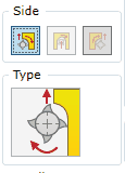
![]() Setting the tool position with respect to the contour being milled
Setting the tool position with respect to the contour being milled
Both a surface and a sketch can be selected as a milling object. The setting of the tool’s position will differ depending on the selected geometry type. Let us examine both cases one by one.
Setting the tool position when the milling object is a part surface
The rotation direction of the spindle is stable and depends on the shape of the mill tool installed in it. The mill tool, while moving with respect to the surface, should do so in the manner so as to avoid damaging the part body. Therefore, the trajectory of the tool must be set off by the tool Radius with respect to the surface. Thus, when changing the side of the contour on which the tool will pass, the direction in which the tool travels along the contour also changes. Also, the setting of the side of the tool with respect to the contour also changes the milling mode:
If the user does not select on which side of the surface the tool should pass, the Mill command will then automatically set the passing direction for Climb milling. This type of milling poses less risk to cut off a wood component during the milling process. However, there occur processing situations where the user may need to apply a milling method where the feed direction of the cutting tool is opposite to its rotation (Conventional Milling). For this purpose, the user has an option of changing the tool position with respect to the surface being milled.
Setting the tool position when the milling object is a sketch
As already mentioned, reference geometry may also consists of 2D sketches drawn by the user. Unlike the above requirement that the mill tool, while moving with respect to the surface, must do so in the manner so as to avoid damaging the part body, in the case of a sketch, this requirement is not applicable because the geometry of the sketch does not carry information about where the part body is located.
Due to this reason an additional option appears allowing the user to Reverse the direction in which the tool travels along the contour without changing the side of the tool with respect to the contour. Thus, in the case of a sketch, you can not only set which side of the sketch line the tool should pass but also reverse the direction in which the tool travels along the contour. Also, with respect to the contour expressed as a sketch, one can request that the tool moves along the contour at the centre of the tool without setting off the tool trajectory to the side. In other words, we can assume that a drawn sketch expresses the tool trajectory itself rather than the desired contour. We get following cases of passes.
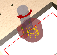
Setting the contour processing direction in the dialog window
As stated above, it becomes clear how the setting of the tool position where the reference geometry is a surface is different from the case where the reference geometry is a sketch. Below are provided two images of the Mill operation’s dialog window which appear depending on which reference geometry is used.
Reference geometry is a surface. Two options are available:
1. The position of the tool to the left of the surface. 2. The movement of the tool along the centre in this case is deactivated. 3. The position of the tool to the right of the surface. 4. The window displays, at a greater zoom level, which milling type is used: the direction of cutter rotation is different than the feed motion (Conventional) or the direction of cutter rotation is the same as the feed motion (Climb).
Reference geometry is a sketch. Two options are available:
1. The position of the tool to the left of the surface. 2. The movement of the tool along the centre. 3. The position of the tool to the right of the surface. 4. The window functions as a button and once you click on it, the movement direction around the skitch is Reversed.
|


![]() Landing of the tool to the starting point of the trajectory
Landing of the tool to the starting point of the trajectory
Sets the landing method of the tool to the starting point of the trajectory. There are two landing options available:
Later these parameters can be edited using the side browser. You should bear in mind that, in case the value for the approach to the trajectory is set as the Ramp landing, the above options are not applicable and the tool in this case will enter the material by landing in a sloped line downward to the first point of the trajectory.
|

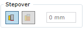
Turns on or off stepover contour milling and allows the user to set the stepover distance.
If the stepover is on, you can indicate the depth of one layer. Note. The functioning of this option is not visualized in the graphic view of the trajectory, but this option will have an impact on the generation of the final CNC program.
|
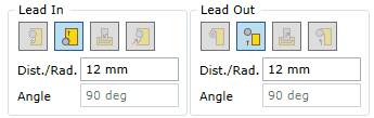
![]() Defining the approach to and withdrawal from the trajectory
Defining the approach to and withdrawal from the trajectory
Certain conditions can be set for the Mill operation: how the tool that has landed to a required height approaches the trajectory and how it withdraws from it. The following two options are available:
These parameters may later be edited in the side browser.
|
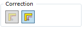
![]() Setting the trajectory correction type
Setting the trajectory correction type
Each method has its own strengths and weaknesses. For example, the tool correction which is usually performed in the machine is rather simple and once faced with a complex contour it is not capable of processing the situation or interprets it incorrectly. However, when designing CAM technology, tasks are performed with approximate tool sizes. For example, the system calculates that the mill tool is 20 mm in diameter, while in fact its diameter (after it is sharpened) may be 19.2 mm. In this way, if we trust the calculations of the CAM system, we may have accuracy problems. On the other hand, the machine contains accurate tool data, thus if the correction is performed within the machine, you can then expect that a required accuracy will be maintained. The user has an option to select the way of indicating a tool milling trajectory: as a trajectory of the tool center or as a mill contour.
|


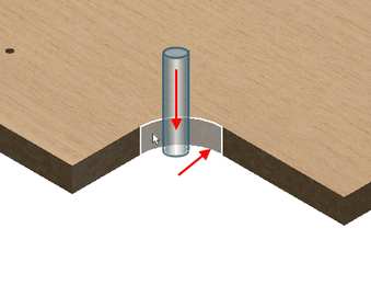
![]() Setting a milling option for corner recesses
Setting a milling option for corner recesses
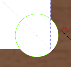
Designers often do not worry about the precision of furniture design. Sometimes there occurs situations where such a discrepancy translates into non-assembly which results after processing contours with the CNC machine. To solve this problem, there is an option which creates an additional mill movement in the recess trajectory corners. This movement helps to mill a pocket and in this way creates a part shape which ensures the joint as shown in the figure below.
In the relevant field, you may indicate the depth to be reached by the mill tool from the corner (see fig. below).
|


![]() Setting breakthrough for milling
Setting breakthrough for milling
When milling contours that go right through the part body, they need to be milled by plunging the mill tool deeper than the bottom of the milled contour. The next parameter called Breakthrough is used for setting this value. One should bear in mind that this parameter does not apply to contours that do not go right through the part body. In this case, the mill tool will pass along the bottom.
|

Setting the oversize for milling. You should bear in mind that a contour will always be calculated in a given situation as if the part is without covers. |