To edit the Tool Pool, you need to move over to the Tool Pool tab in the CNC machine configuration dialog.
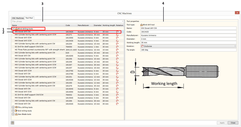
The appearing dialog window is divided into two spaces:
| ▪ | On the left hand side, you see the content of the Tool Pool. |
| ▪ | On the right hand side, you see a window for entering and editing data about a specific tool. |
| 1. | The tool item section by tool type. Click here for more information about available tool types in the Woodwork for Inventor CAM system. Each section may be collapsed or expanded using the icon |
| 2. | Tool data item row. Items are displayed in the form of a table. The meaning of each column can be found in the table cap which is shown in the top of the window. All tool items within the section may be grouped by a selected column. To do this, you simply need to place the cursor on the column name in the table cap and click the left mouse button. If you need to group items based on several criteria, select the next column name and repeat the above step while pressing and holding the Ctrl key. The context menu of each item is opened by clicking the right mouse button. |

Using this menu, you can:
Add: add a new tool of a selected type to the database.
Copy: copy the selected tool.
Delete: delete the selected tool.
| 3. | Selection window. Tools are filtered based on the filtering phrase entered in this field. Selection is performed through all displayed data fields. |
| 4. | Tool data input tab. The form of this tab differs depending on the type of the defined tool. Further we will provide the description of the data input window for each tool type. |
![]() Blind Drill data input form
Blind Drill data input form
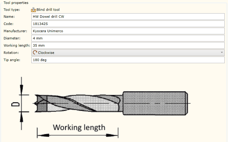
Name |
Original name which has been assigned to the tool and which is contained in the tool database.
|
||||
Code |
Original code which has been assigned to the tool and which is contained in the tool database. It is usually a tool code from a manufacturer‘s catalog.
|
||||
Manufacturer |
The manufacturer of the tool.
|
||||
Diameter |
The working diameter of the tool. You should bear in mind that this diameter is used in the automatic hole recognition process. If the hole type and diameter matches the diameter of this tool, it is considered that the first condition for processing this hole has been met. Another condition is that the spindle orientation must match the hole orientation in space (for more information, click here).
|
||||
Working length |
The length of the working part of the tool. This value (just as the diameter) serves as a limitation which is used when making a decision whether the hole can be processed. If the hole depth plus breakthrough depth is greater than the working length of the tool, such a hole will be interpreted as non-processable despite the fact that other limitations meet processability criteria.
|
||||
Rotation |
Rotation direction of the tool. Possible values:
|
||||
Tip Angle |
The tip angle of the tool.
|
||||
Tool image |
An open file dialog window is opened by placing the cursor on the image and clicking the left mouse button. You may change the tool image which should not exceed 200kB. |
![]() Through Drill data input form
Through Drill data input form
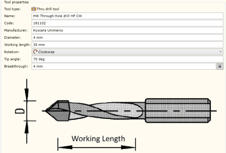
Name |
Original name which has been assigned to the tool and which is contained in the tool database.
|
||||
Code |
Original code which has been assigned to the tool and which is contained in the tool database. It is usually a tool code from a manufacturer‘s catalog.
|
||||
Manufacturer |
The manufacturer of the tool.
|
||||
Diameter |
The working diameter of the tool. You should bear in mind that this diameter is used in the automatic hole recognition process. If the hole type and diameter matches the diameter of this tool, it is considered that the first condition for processing this hole has been met. Another condition is that the spindle orientation must match the hole orientation in space (for more information, click here). |
||||
Working length |
The length of the working part of the tool. This value (just as the diameter) serves as a limitation which is used when making a decision whether the hole can be processed. If the hole depth plus breakthrough depth is greater than the working length of the tool, such a hole will be interpreted as non-processable despite the fact that other limitations meet processability criteria.
|
||||
Rotation |
Rotation direction of the tool. Possible values:
|
||||
Tip Angle |
The tip angle of the tool.
|
||||
Breakthrough |
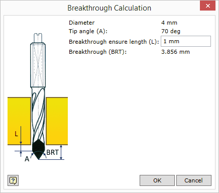
Tool breakthrough size required to ensure a clean bottom hole edge. At the end of the row there is a breakthrough calculator start button
|
|
||
Diameter |
Displays the diameter of the given tool.
|
|
Tip Angle (A) |
Displays the tip angle of the given tool.
|
|
Breakthrough ensure Length (L) |
Allows the user to enter the value (L) ensuring the breakthrough of the straight part of the drill is beyond the bottom hole boundary.
|
|
Breakthrough (BRT) |
Displays the calculated height of the top to which the value (L) has been added. By pressing the "OK" button, this size will be entered in the Breakthrough value. This value is only intended as a recommendation and it can be edited in the Breakthrough window.
|
Tool image |
An open file dialog window is opened by placing the cursor on the image and clicking the left mouse button. You may change the tool image which should not exceed 200kB.
|
![]() End Mill data input form
End Mill data input form
|
|
Name |
Original name which has been assigned to the tool and which is contained in the tool database.
|
||||
Code |
ĮOriginal code which has been assigned to the tool and which is contained in the tool database. It is usually a tool code from a manufacturer‘s catalogue.
|
||||
Manufacturer |
The manufacturer of the tool.
|
||||
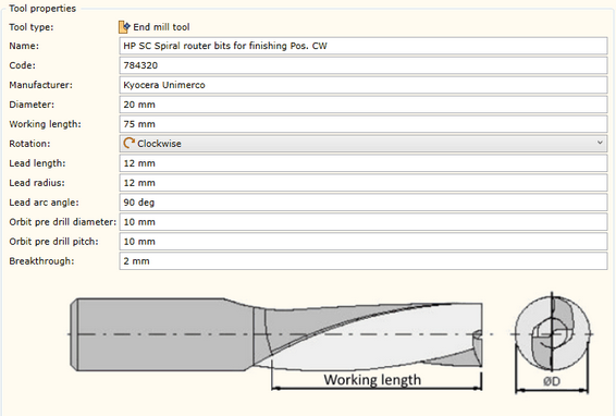
Diameter |
Working diameter of the tool. . |
||||
Working length |
The length of the working part of the tool. This value serves as a limitation which is used when making a decision whether the contour can be processed. If the contour depth is greater than the working length of the tool, such a contour will be interpreted as non-processable with the given tool despite the fact that other limitations meet processability criteria.
|
||||
Rotation |
Rotation direction of the tool. Possible values:
|
||||
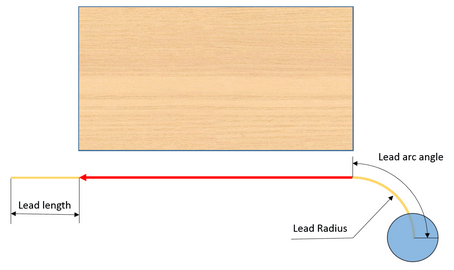
Lead length |
The distance between the tool lead in and lead out line from the start and end point of the contour being milled (see fig. above). This value is provided as a default value while setting parameters for the Mill operation.
|
||||
Lead radius |
The arc Radius of the tool lead in and lead out in an arc motion from the start and end point of the contour being milled (see fig. above). This value is provided as a default value while setting parameters for the Mill operation. One should bear in mind that the arc Radius is always defined for the trajectory which is offset (Software calculated) by the tool Radius. If a non-offset (Hardware calculated) contour status is used, the arc radius is automatically corrected based on the specified arc radius in the offset status. For more information, see the description of the Mill operation.
|
||||
Lead arc angle |
The arc angle of the tool lead in and lead out in an arc motion from the start and end point of the contour being milled (see fig. above). This value is provided as a default value while setting parameters for the Mill operation.
|
||||
Orbit pre-drill diameter |
The diameter of the mill orbit entry into the material. This orbit diameter is used if an orbit entry into the material is requested during the Mill or Pocket operation. One should bear in mind that the orbit diameter is always defined for the trajectory which is offset (Software calculated) by the tool Radius. If a non-offset (Hardware calculated) trajectory calculation is used, the orbit Radius is automatically increased by the size of the tool radius but the editing process still uses the orbit radius defined for an offset trajectory.
|
||||
Orbit pre-drill pitch |
The diameter of the mill orbit entry into the material. This orbit diameter is used if an orbit entry into the material is requested during the Mill or Pocket operation. One should bear in mind that the orbit diameter is always defined for the trajectory which is offset (Software calculated) by the tool radius. If a non-offset (Hardware calculated) trajectory calculation is used, the orbit Radius is automatically increased by the size of the tool radius but the editing process still uses the orbit diameter defined for an offset trajectory.
|
||||
Breakthrough |
The default breakthrough depth size if the contour is cross-milled during the Mill operation.
|
||||
Tool image |
An open file dialog window is opened by placing the cursor on the image and clicking the left mouse button. You may change the tool image which should not exceed 200kB.
|
![]() Saw Blade data input form
Saw Blade data input form
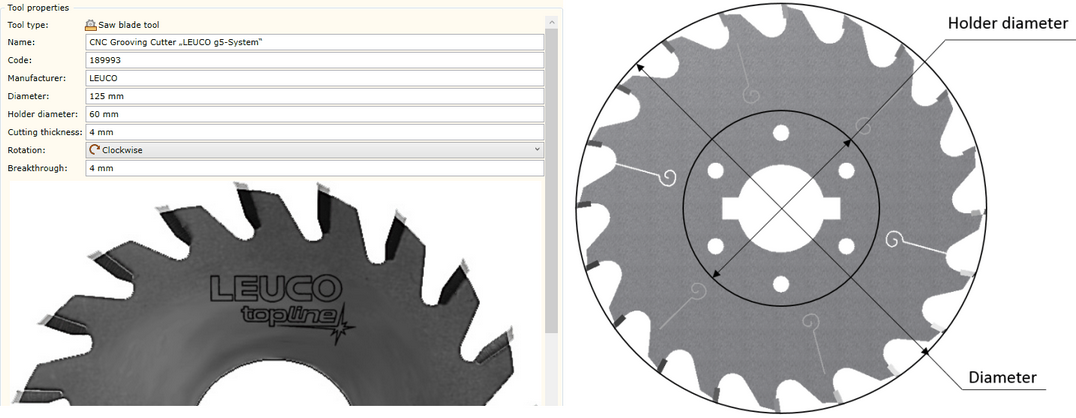
Name |
Original name which has been assigned to the tool and which is contained in the tool database.
|
||||
Code |
Original code which has been assigned to the tool and which is contained in the tool database. It is usually a tool code from a manufacturer‘s catalogue..
|
||||
Manufacturer |
The manufacturer of the tool.
|
||||
Diameter |
Working diameter of the tool.
|
||||
Holder diameter |
The diameter of the tool holder. This holder diameter along with the working diameter of the tool allows the calculation of the maximum cutting depth when performing Groove and Cut operations. In addition, it serves as a limitation required for making a decision about the processability of the part of selected geometry in the model.
|
||||
Cutting thickness |
Cutting thickness of the tool. This value is used as a limitation that prevents the processing of the grooves narrower than the cutting thickness. In addition, this value is used when calculating the number of passes if the groove is wider than the cutting thickness.
|
||||
Rotation |
Rotation direction of the tool. Possible values:
|
||||
Breakthrough |
The default breakthrough depth size in the Cut operation.
|
||||
Tool image |
An open file dialog window is opened by placing the cursor on the image and clicking the left mouse button. You may change the tool image which should not exceed 200kB. |
