When looking for the optimal clamping option, many criteria should be taken into account. Each clamping option is considered taking into account each criterion. This results in a score that affects the overall assessment of the clamping option. CAM solver calculates the score for each possible clamping option and selects the best one. All criteria are ranked and the user can adjust the importance (weight) of each criterion. This allows the user to have a say in the operation of CAM solver. Below are the criteria that affect choices made by CAM solver.
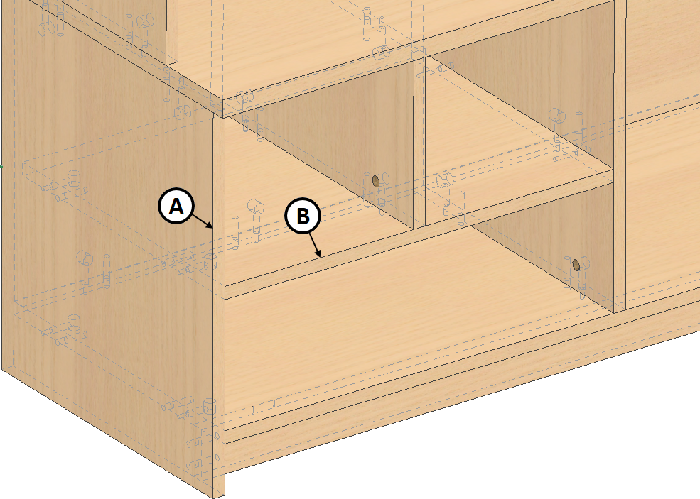
All manufacturing processes have inaccuracies defined as dimensional tolerances. For example, size tolerance for the cutting of a workpiece from a board can be 0.5–1.5 mm. When manufacturing high-quality furniture, this may have an adverse effect in further manufacturing steps. Let’s take a typical body of a piece of furniture (see the figure below).
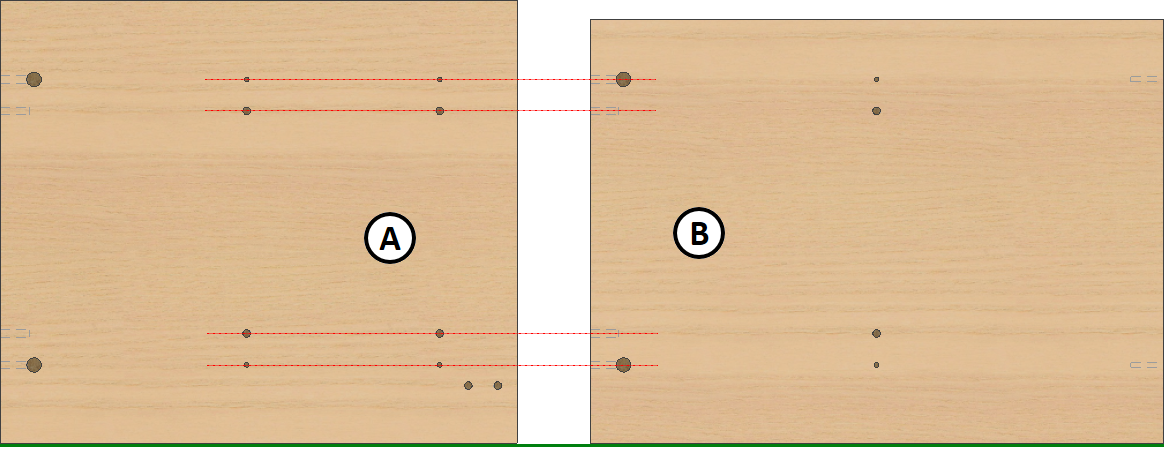
Let’s take two parts: A and B. As we can see in the figure above, it is essential to ensure precision when drilling the holes, because facade edges (green line) have to match perfectly when assembling the piece. However, as mentioned above, some unwanted errors occur. Therefore, correct choice of a clamping option could help eliminate (or increase) the effect of such errors on the quality of furniture. How does this happen?
 Clamping workpieces on opposite sides results in an unwanted misalignment of the parts on the facade side of the piece of furniture at the time of assembly
 Clamping workpieces by supporting facade edges of both parts eliminates the risk of misalignment of the parts on the facade side of the piece of furniture at the time of assembly
It can be argued that CNC machining follows the measurements calculated from the starting point of the clamping coordinate system very accurately. Orange color in the figures marks cutting tolerances with different clamping options. As we can see in the above figure, failure to adjust the arrangement of parts (taking into account the position of both parts in the assembly) leads to a situation where the cutting error affects CNC machining and results in an unwanted misalignment at the time of assembly of the piece of furniture.
If you take into account the position of both parts in the assembly and choose correct arrangement base for the parts, misalignment caused by the error will occur at the back of the piece of furniture which will have less significant impact on the quality.
Conclusion. Clamping of a part in a CNC machine affects quality and depends on the position of the part in the completed assembly.
Woodwork for Inventor allows specifying the direction faced by the front of the assembly. Based on this direction, the program determines the workpiece plane, which becomes the base plane. The latter has to be supported against clamping jaws of a CNC machine. The position of the base plane is taken into account when automatically generating CNC technologies and clamping options are created accordingly. By the way, in some cases, the direction of base plane search does not coincide with the direction of the assembly facade. For example, the sides of a drawer are aligned according to the top, so for this type of assembly, the direction of base plane search will be top. The user can decide on the best direction for the specific piece of furniture or its part. Sometimes the direction of base plane search is not specified or has no meaning. In such event, CAM solver relies on other criteria necessary to determine the correct clamping option.
 Base planes of parts found based on the specified facade direction
If the direction for base plane search has not been specified by the user, one of the plane normals of the View Cube will be used as a default search direction. The user specifies the plane of the aforesaid cube that is treated as determining the search direction, when configuring CAM solver behavior in clamping settings.
Information about ways to specify the base plane direction is given in the command description.
|
In some situations, the direction for base plane search is not specified for certain parts or it has no meaning. Typical situation:
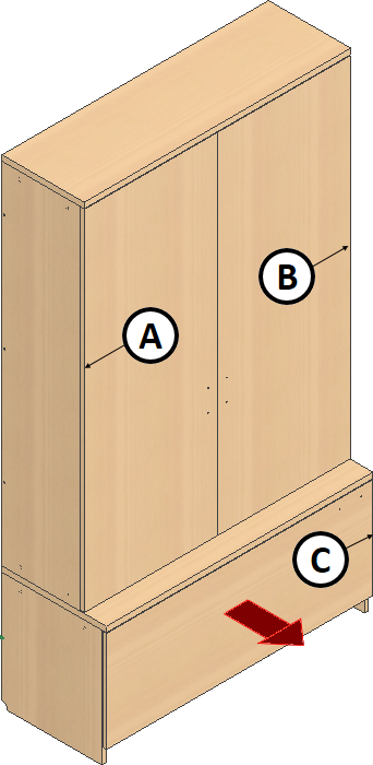
The specified direction of base plane search shown in the figure has no meaning with facade parts (see figure above: A, B, C). The direction of base plane search can be specified for each individual door. Woodwork for Inventor command which is used to specify the direction will not prevent this. However, this is not convenient. In such event, where no direction for base plane search is specified for the given part, another clamping criterion has to be taken into account.
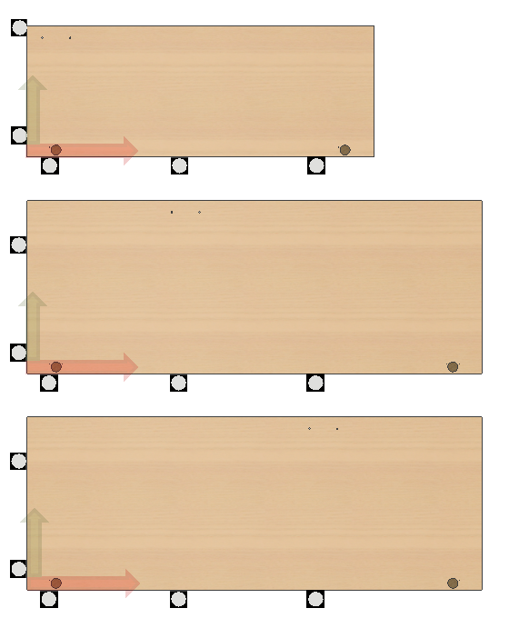
CAM solver gives higher scores to clamping options, where larger holes are closer to base supports (see figure above). This way, clamping options where cutting errors (see figures below) do not lead to hinge holes being drilled at a different distance from the edge are scored higher.
|


Additional requirement is set for the placement of workpieces. It is done along the specified axis of the coordinate system of the machine. Usually, it is X axis, but with some specific machines, the user can request rotation along Y axis. CAM solver gives higher scores to clamping options that satisfy the specified criterion.
|
If the size of the working area was specified when configuring the CNC machine, CAM solver takes this into account and reduces the score calculated for the criterion.
|
Each clamping option is analysed in terms of the number of operations that can be performed with it. Higher scores are given to clamping options offering higher number of operations. The scores are given individually for drilling, milling, grooving and cutting operations. Therefore, when rating these individual criteria, the user can give more weight to certain operations.
|
If full machining cannot be performed with a single clamping option, CAM solver creates other required clamping options to complete machining. CAD solver attempts to create the first clamping option that does not cross the external loop of the workpiece. This is done so that the part can be based once it is flipped over.