Opening CAM Environment
To create CAM technologies for a part, it is necessary to access CAM environment of Woodwork for Inventor plug-in. Two options are available here:
| 1. | Accessing Woodwork for Inventor CAM environment from the part design environment. In such event, in the top menu line, select Environments tab and, in the toolbar, click the icon shown below. |
WoodworkCAM ![]()
The fact that you have entered CAM technology design environment is evidenced by toolbar with CAM technology creation tools as well as different content of side browser with WCAM pane written at the top.
| 2. | Accessing Woodwork for Inventor CAM environment from the assembly design environment. This is done from Woodwork Design toolbar using CAM status highlight function. |

Clicking this button initiates the analysis of the opened assembly and shows the status of each part.

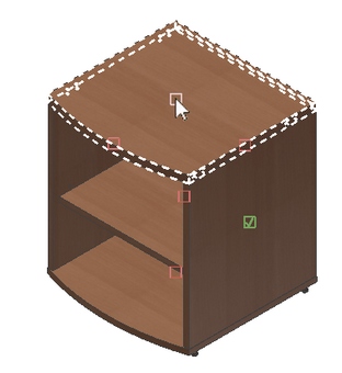
3. The following CAM status symbols are available:
☐ - red hollow rectangle means that the part has never been opened in CAM environment and does not have CAM technology created for it.
☑ - green rectangle with a tick in the middle means that the part has CAM technology created for it.
☒ - green rectangle with a cross means that the part has never been opened in CAM environment, but the user closed it without creating any processing operation. This means that the user has viewed the part, but decided not to create any technology for this part. Such parts usually are set-in shelves, cardboard backs, etc.
Once you point cursor to such symbol, the part is highlighted; if you click left mouse button (LMB), the part is in Woodwork CAM environment.
Stages of Workflow
To create CAM technology, it is necessary to follow certain working order. Such order is as follows:
| 1. | Create a Job for the part. Specify the machine to be used for the job, for which CAM technology will be created. Several jobs can be created for one part. This happens in cases, where processing of the part is performed using several machines, or where it is necessary to prepare processing of the part for several alternative routes. |
| 2. | Specify the base point or, in other words, create Clamping for the part. One part can have several clamping options. This depends on the form of the processed part and technological capabilities of the machine. |
3. Create processing operations. Currently, Woodwork CAM supports creation of the following operations:
| a. | |
| b. | |
| c. | |
| d. | |
| e. | |
4. Generate CNC programs.
Before moving on to a detailed description of ways to create and manage data of the above stages, the next section explains how to configure the machine, for which technology is being created, and the impact of such configuration on the creation of CAM technology.