The command performs the arrangement of joints or other standard components in the assembly model. It is performed based on the iMate arrangement constraints pre-written in the component. The component is arranged based on the relevant geometry in the assembly model consistently specified for each assembly constraint. This command has a several default modes:
▪Single – where one geometric element is specified for one constraint in the model. An example can be a plane on which an axis is arranged: in this case, a component arranged to implement a constraint immediately changes its spatial position.
▪Multiple – where several geometric elements are specified for one constraint in the model. In this way, for the arranged component you may specify that its axis should be arranged based on several spatial planes. Then the command allows specifying a required geometry in the model for each assembly constraint, and inserting a new unit of the component being arranged in each available constraint realization position.
To start the command, go to:
Woodwork Design –> Joint –> Attach ![]()
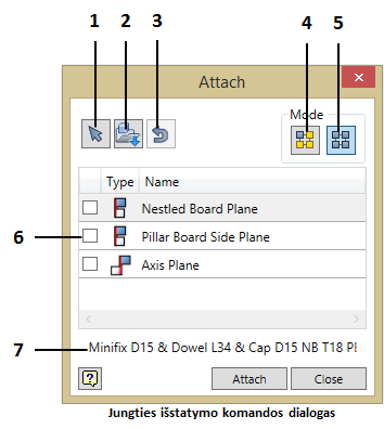
1. On screen- selection of the hardware component.
2. Hardware component selection from the specified catalogue on the disk.
3. The use of the component lasted used in the command for performing the next arrangement.
4. Enabling the single arrangement mode.
5. Enabling the multiple arrangement mode.
6. A space where the iMate assembly constraints of the selected component are represented. Unchecking the box means cancelation of the selected assembly constraints and re-enabling selection of the specified constraint.
7. Part Name of the component unit.
The command is executed by clicking the “Attach” button.