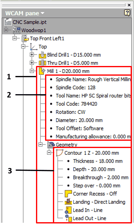
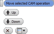
Once an operation has been created, a mill operation’s node will appear in the side browser.
Let us look at the content of this node and editing options for this operation.

1.Mill operation node. The operation is assigned with the name "Mill" and the order number. Also next to it is presented a tool diameter separated by a hyphen. 2.Spindle data along with the data of the tool mounted in the spindle. Next to this, in the last rows of this data block, the following information is provided: a.Tool Offset - how the tool trajectory is calculated. b.Manufacturing allowance - what processing oversize was used when creating an operation. 3.The geometry block contains information as to where each separate generated trajectory is registered as a contour. The following data is stored here: a.Thickness: The height of the milled contour. b.Depth: The milling depth calculating from the working plane to the tool tip during the final pass. c.Breakthrough: the value of the extra milling depth. d.Stepover: Stepover milling depth. e.Corner recess - The value of the corner recess milling option. f.Landing - The landing method of the tool. g.Lead In: The method of the approach to the mill contour. h.Lead Out: The method of the withdrawal of the tool from the mill contour.
|
The operation node has the following context menu:
Changing of the trajectory calculation method
Tool offset: brings up the node’s context menu. You can select a method opposite to the current one. Or you can do this by double-clicking the left mouse button.
Editing the data of the geometry block
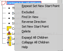
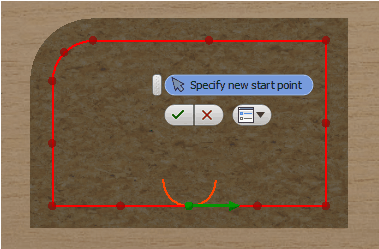
You can change the name of the geometry node. Also a context menu can be brought up where you can find the following options:
Also, the following parameters of the subnodes of the geometry node can be edited:
|


