Once you move over to the CNC machines dialog tab, you will see the following:
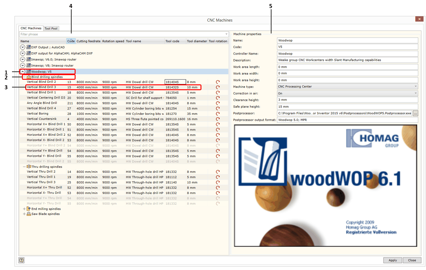
1.Here you can see a list of the CNC machines that have been created. Each node in this list can be expanded or collapsed using this icon
The following operations can be performed: 2.The spindle group of a given machine which can be expanded or collapsed using the symbol +/-. There are four spindle groups:
There is also an additional spindle group (Tool-less spindles) which appears when a new spindle has been created and this spindle has not yet been set up with a tool. Click here for more information about spindles. 3.Spindle description. The list of spindles of a given group is presented in the form of a table. This table contains the following spindle characteristics:
4.Selection field. Spindles are filtered based on the filtering phrase entered in this field. 5.CNC machine data description tab. This tab is visible while the cursor is placed on the CNC machine node. Once you move over to the spindle item, the screen on the right hand side will change to the spindle data editing table. In the CNC machine data description tab, you can enter and edit the following data:
|
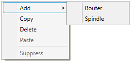
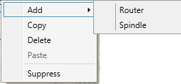
As mentioned earlier, the spindle data container may be created through a context menu in one of the following two ways:
▪By copying (Copy): spindle data is copied to the buffer, and using the Paste feature a spindle copy may be created in the same CNC machine. Or you can place the cursor on another machine and the copy will be respectively placed in another machine. ▪By creating a new spindle: a new "empty" spindle will be created which will be automatically included in the Tool-less group. Once such a spindle is set up with a tool, it is automatically removed from the above group (Tool-less) and transferred to a relevant spindle group.
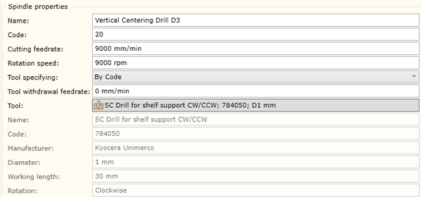
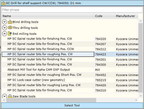
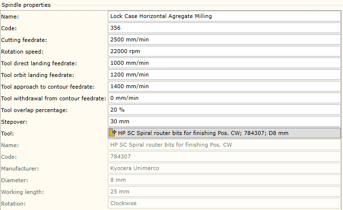
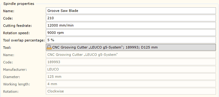
To edit spindle data, you need to place the cursor on the spindle data node on the left hand side of the window. Then a tab will appear on the right hand side of the window displaying the data of a given spindle. The spindle data tab will differ depending on the tool that has been setup in the spindle. When changing the tool, the spindle group will be automatically changed along with the data fields describing the spindle.
Below you will find the description of the data editor window for each group.
The data of the tool selected in this window that cannot be edited are displayed below in grey.
|
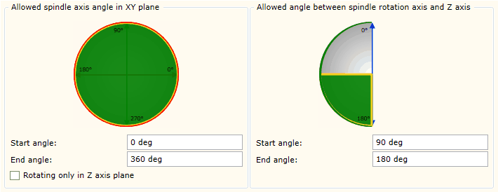
For each group of spindles, the same interface is used to define the degrees of freedom for the spindle during a working movement.
On the left hand side of the dialog window you can see the spindle capabilities to change the spindle axis orientation in XY plane, and on the right you can see its capabilities to change the orientation of the spindle axis in XZ plane. For more information, click here.
▪Start angle: start angle of the segment. ▪End angle: end angle of the segment.
The values of the start and end angles of the segment in XY plane is defined within the range of 0 to 360 degrees. The values of the start and end angles of the segment in XZ plane is defined within the range of 0 to 180 degrees. Value 0 indicates that the spindle axis is oriented upward, whereas 180 degrees means that it is oriented downward.
Rotating only in Z axis plane: this option is currently not used. |
