One of the tasks that the furniture constructor faces is to provide dimensions for furniture parts and their workpieces in different specifications. As mentioned earlier, a furniture part is, in essence, an assembly glued from a workpiece with a fill material, and covered with cover material workpieces. A separate modeling of Autodesk Inventor fill material and cover is a labor-intensive and time-consuming task. Besides, this overburdens a computer-based furniture model.
Woodwork for Inventor fixes the above problem because it has a material assignment command allowing the user to assign a fill to an Autodesk Inventor part and assign covers to separate part faces. Such a method enables the user to fully define furniture parts without overburdening the design process with unnecessary tasks. Sometimes, however, it can be unclear as what – a furniture part or a furniture workpiece – is modeled in the CAD system during the design process. In some situations during furniture modeling it is more convenient to model a workpiece, while in others it is more efficient to model a part.
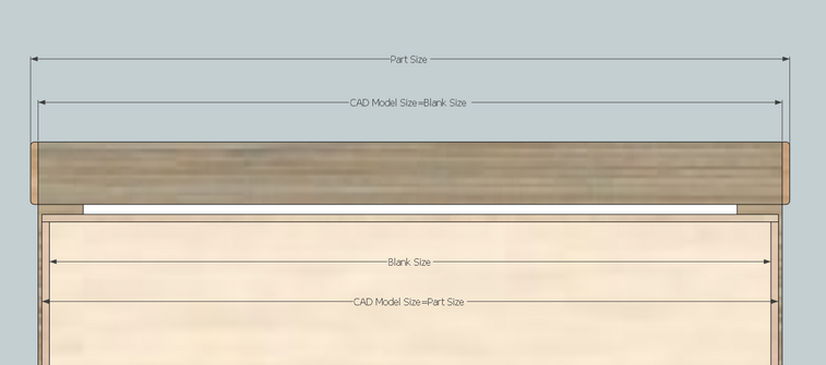
Size calculation for edge band position “On Top” and “Sunk”
For instance, when modeling a drawer, it is more convenient to model the top of the container cabinet as a workpiece, later defining that the edge band of the part that will be attached to this workpiece. In other cases, for example when modeling a cabinet door, it is convenient to model the final dimension of the part, by specifying that the edge band placed on the part is “sunk” within the CAD model volume. Therefore, the dimensions of the door workpiece should be proportionately reduced in the estimates.
Woodwork for Inventor provides the opportunity to indicate whether a cover should be calculated as “attached” to the CAD model or “sunk” within the CAD model volume (it is called cover positioning with respect to the CAD model). Based on the above, two sets of dimensions are calculated:
| ▪ | Part Size: obtained after the production of the part is completed, i. e. after the part is cut from a fill material, mechanically processed (if needed) and coated with required covers. |
| ▪ | Blank Size: obtained and required when the part is being cut from a fill material. |
The above sizes may differ significantly from each other. This depends on the technology of the part production, materials used and grain direction.
During the initial material assignment, Woodwork for Inventor automatically sets the grain direction. The grain direction algorithm searches for the largest flat Face and the two longest edges on that face that are perpendicular to each other. If this is not achieved, other rules are applied which allow setting the initial grain direction of the material. If the constructor is not satisfied with the grain direction that has been automatically set, he may modify it using the Woodwork for Inventor tools, by specifying a different face or different grain vector orientation.
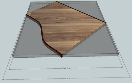
Change in the blank size due to the change in the grain direction
Woodwork for Inventor takes into account the grain orientation and based on it automatically generates reports with required workpiece size.
When performing additional mechanical processing, there is an option for indicating additional oversizes for a workpiece as shown in the figure below. The Woodwork for Inventor add-on has oversize control tools. Workpiece oversizes can be indicated both for fill materials and veneer covers.
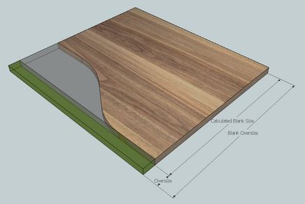
Change in the blank size due to the added oversize
Note. When assigning covers to parts, Woodwork for Inventor does not make any changes to the CAD model geometry. All cover assignments to a workpiece only affect the data contained in the reports generated by Woodwork for Inventor.