Assembly design methods |
  
|
Assembly design methods |
|
Autodesk Inventor has few of methods how to create design. These methods are specified as:
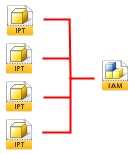
The essence of the ‘Bottom Up’ Technique is that each part is created individually, and then all the parts are inserted into an Assembly and constrained to each other.
There is no link created between the parts, the parts fit together because you designed them to fit together. If you change one part, you’d better know which other parts will be affected by the change and make sure that they are updated accordingly!
This technique works well for small assemblies with only a few parts and, of course, if you want to show mechanical motion – you will have to use constraints. However, on large assemblies one change to a key part can lead to a ‘House of cards’ effect which can leave to you spending all afternoon straightening out a mess of cross part fits and constraints.
This technique can be used effectively on large assemblies which are built from many ‘Stock’ components that aren’t subject to change.
|
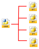
This technique makes it easy to use Inventors ‘Adaptive’ sketches and features to link parts together in the Assembly. This creates an Assembly model that is controlled by a ‘Master’ part (or a series of Master parts). This is a great way of ensuring that parts that need to fit together always fit together, without any help required from you.
This technique is extremely intuitive and quick. On the downside you can still get yourself into a right pickle if you manage to build any self-referencing loops, so this technique is still only appropriate to small to mid size assemblies, where cross part relationships are readily apparent.
One needs to point out that Adaptive parts are re-calculated every time you perform a local or global regeneration, so they place quite an overhead on your PC.
In the tutorial that demonstrates this technique I show how you can turn ‘Adaptivity’ on and off, to speed up Inventor’s performance.
|
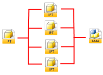
Basically, you create all your Parameters and sketches in one part file and then Derive the required parameters and geometry into separate part files*. You then build your part features in each part file using this shared geometry.
The beauty of the technique is that when you come to place your parts into an assembly, no constraints are required! You can simply insert all you parts at their origins and ground them.
No constraints are required because all the parts are in the right place. Any changes to the underlying geometry in the ‘Skeleton Model’ part file will be propagated through all the parts that are based on the Skeletal model.
You can still ‘Un-ground’ a part and build in constraints if you need them. There is usually no call for Adaptivity, because the cross part relationships are handled outside of the Assembly model.
This technique would not necessarily be appropriate for Assemblies that use all ‘Stock’ parts. It is important to remember that the ‘Skeletal’ model file must be managed along with the rest of the files that make up the assembly. This technique is very useful when you are creating a model that uses a large number of Bespoke parts, that will not be useful in other assemblies.
|
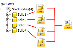
Inventor 2010 allows us to create ‘Multi Body’ parts. Each body could be used to represent a separate part. This modelling technique is similar to ‘Skeletal’ modelling, except that we can ‘Derive’ a whole Body out into a part file to create a new part.
In this technique we can model an entire assembly in a part file, and use Inventor 2010’s ‘Make components’ tool to automatically create a derived assembly based on the Master part.
Similarly to ‘Skeletal’ modelling, no constraints are required – all the cross part relationships are managed via the ‘Master’ part file.
Once again, this technique is excellent for creating assemblies with a large number of Bespoke parts.
On the WEB sites you can find a lot of examples how to use each of the design methods. |
Woodwork4Inventor does not impose any specific requirements for using design methods. However Multi Body Master Part Method seems more appropriate method to create furniture than other methods. This method allows to build and make design modifications of complicated wooodwork 3D models in a simple and elegant way.