Typically, the outer contour of a part to be milled in shape nesting is calculated automatically when creating CAM technology for nesting.
In the rare cases when the program is unable to determine the nesting contour from the geometry of the part or the nesting contour does not match the contour of the part for any technological reason whatsoever, the user can create the contour themselves and it will be used for nesting design.
Any sketch that meets the following requirements can be declared a shape nesting contour:
| 1. | It is on the reference plane of the part or on the side opposite to the reference plane. |
| 2. | The contour is not branched and is closed. |
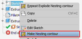
The contour is created using the context menu of selected sketch.
Important! Different from automatically created contours, a custom nesting contour created by the user does not take account of edge banding of the part and the position of the band with respect to the edge. Therefore, when designing the edges in the sketch, the user must take this into account and adjust the contour accordingly.
A part can have only one shape nesting contour.