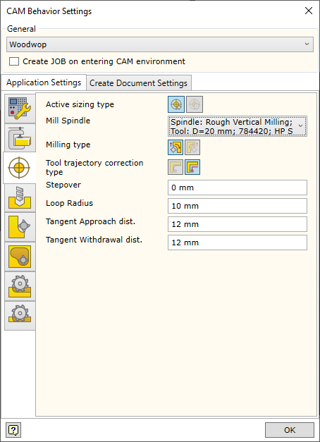
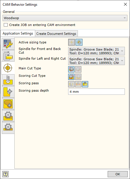
Sizing operations can be performed by mill around the edges or cutting by saw lengthwise and crosswise. Therefore, when setting up the CAM solver for automated technology, the tool to be used for part sizing and operation parameters have to be specified. An active sizing method is the one selected from the Active sizing type field.
|
|
|
Sizing by Mill
|
|
|
Mill Spindle |
Mill spindle selector |
|
Milling type |
Setting the side, from which the loop is followed, and the milling type. More information is available here. |
|
Tool trajectory correction type |
Setting the correction type. More information is available here. Keep in mind that in cases, where the calculation method of machine trajectory is given as the original loop, it is impossible to ask the programme to generate a repositioned loop. |
|
Stepover |
Setting the layer-by-layer milling step. |
|
Loop Radius |
Setting the corner bypass loop radius. More information about this parameter is available here. |
|
Tangent Approach dist. |
Setting the distance of approach to the milled sizing loop. |
|
Tangent Withdrawal dist. |
Setting the distance of withdrawal from the milled sizing loop. |
|
|
|
|
Sizing by Saw
|
|
|
Spindle for Front and Back Cut |
Setting the spindle for trimming the workpiece lengthwise (front and back). |
|
Spindle for Left and Right Cut |
Setting the spindle for trimming crosswise (left and right) |
|
Main Cut Type |
Setting the main cut type. More information is available here. |
|
Scoring Cut Type |
Setting the scoring pass cut type. More information is available here. |
|
Scoring pass |
Options for the turning on/off of the scoring pass. More information is available here. |
|
Scoring pass depth |
Setting the allowance of the material left after the cut. |
|
|
|

