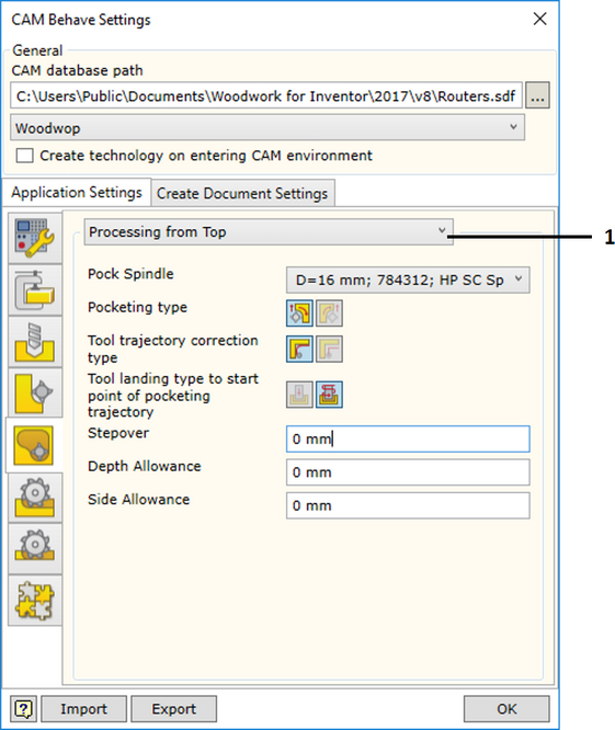
Pocketing operation has parameters controlling various aspects of the technology being created, such as: milling type, tool lead in type, etc. The technology is created for all spindles included in the configuration of the machine, thus pocketing operation settings may differ for the processing using top oriented, side oriented or free oriented spindle. Therefore, the software allows the user to adjust these aspects separately for top oriented, side oriented and free oriented spindle.
These settings are accessed from the pocketing operation settings tab.

1. Orientation Selector |
The selector allows choosing spindle operations for which the settings specified below will be applied. The following options are available:
Different spindles and different operation parameters can be specified for individual orientations.
|
||||||
Pock Spindle |
A machine spindle is selected for the spindle orientation selected in the selector. Below, parameters of the operation created by CAM solver for this spindle are defined.
|
||||||
Pocketing Type |
Setting the milling type for the pocketing operation. To read more, click here.
|
||||||
Tool Trajectory Correction type |
Setting correction type for the final milling contour. Keep in mind that in cases, where the calculation method of machine trajectory is given as the original contour, it is impossible to ask the program to generate repositioned contour.
|
||||||
Tool landing type to start point of pocketing trajectory |
Setting tool landing type to the start point of the pocketing tool trajectory. To read more, click here.
|
||||||
Stepover |
Milling stepover.
|
||||||
Depth Allowance |
Depth allowance for the milled pocket.
|
||||||
Side Allowance |
Side allowance for the pocket. |