In order to start nesting design, each part must have CAM technology created. It can be created automatically or manually. The technology is created manually as follows:
CAM environment can be opened in several ways, which are described in detail in the section Opening the CAM environment and requirements for workflow steps.
The simplest way to access it is to open a part with assigned Woodwork for Inventor material and open CAM environment through the toolbar:
Woodwork Design->
|
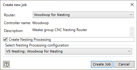
Woodwork CAM->Job
A detailed description of the functioning of the command is available in the section Job creation.
|
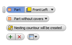
Once the device for CAM technology is specified, the clamping must be set, at the same time specifying the base point for the part in CAM technology.
Woodwork CAM->Clamping
If a nesting routing process was created, the clamping command is slightly different from the clamping used in CNC workcentres. The differences are as follows:
Thus, if a nesting routing process and clamping are created, a part can be included in the Nesting program for shape nesting design.
However, if a full CAM technology is necessary, the remaining CNC operations have to be created.
|