Along with the installation of Woodwork for Inventor, several examples are provided to help you get a better understanding of how Macro works, and to give you a starting point for designing your own cutting components with Macro processing.
Macro examples include: C:\W4INV <Inventor version number> Design\PROJECTS\Samples\Macro DEMO Examples
As mentioned at the beginning of this section, all examples are designed to work with Woodwop V6.0 and the CAM system. Some of the Macro models require some preparatory work. If the Macro function in the example uses exclusively Woodwop’s standard functions, then no preparation is required. For those Macros that call Woodwop Macros created for the given example, it is necessary to copy them to the Woodwop system directories where all the Woodwop Macros are stored. This is usually the C:\MACHINE1\Control\c1\data\cnc\ml4\Macros\ directory. However, depending on the Woodwop installation and configuration, the location may vary, so for those JS Macro programs where a Front-End Macro call is made, the appropriate path changes must be made. To put it briefly, before running the samples, please read the ReadMe document available in the directory of each sample. This document describes the preparatory steps needed to run the samples successfully.
Here you will find the following examples:
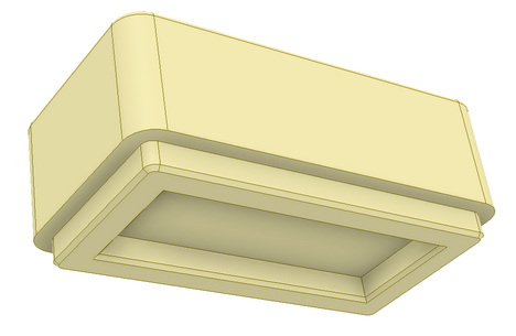
Example “Holder for paper clips.ipt”, which demonstrates how to transfer the parameters of a cut component to a Macro program. In this way, by adjusting the size of the sculpted pocket required for the component, it can be built into a furniture desktop. No additional Macro repositioning is required, as Woodwop’s Trimming Pocket Vertical function is used.
 Paper clip holder
|
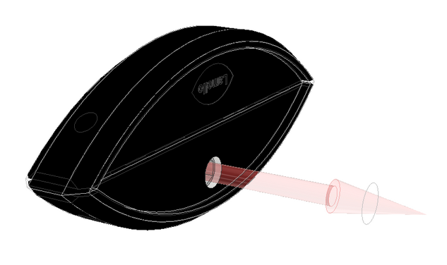
Example “Table top pencil case.ipt” demonstrating two ways in which the rotation angle of the Front-End Macro can be transferred to the Front-End program.
There are two possibilities:
In the example, both methods are implemented.
The Front-End Macros required for this example are “Program used Rectangular cut by Angle Macro.mpr” and “Program used Rectangular cut.mpr”, which need to be loaded into the Woodwop Macro library.
|
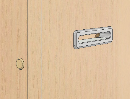
Examples in “Aisle.ipt” and “iAisle.ipt” demonstrate how the alternate side processing can be used.
The opening required for the wire pass-through component can be milled from either side of the board, so the component has alternate side processing in it. An example of an iPart type component is also shown here.
This example requires a Front-End Macro “MacroDive.mpr”, which must be loaded into the Woodwop Macro library.
|
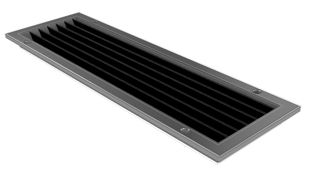
Example demonstrating the possibility of using multiple JS Macro definitions to process a component opening.
This component uses the Woodwop library Macro “Makros/2_routing/5_axis/edge_cutting.mpr\” and the standard Woodwop function “Trimming Pocket Vertical”.
|
Example “Clamex P-14 Connector.iam”, which demonstrates a component that is built as an assembly and has an effect on the two parts of a piece of furniture to be joined. Also, this example shows how the component works if it can be positioned in the space at any angle. In addition, here you will see an example of how the reference coordinate system can be used to work with the oversizes in Woodwork for Inventor, which are further linked with the interpretation of the oversizes in the Woodwop post-processor.
This example requires a Front-End Macro “Lamello_Saw_Processing.mpr”, which must be loaded into the Woodwop Macro library. Also, a description of the special tool needs to be loaded here for the Woodwop system. Please refer to the ReadMe.pdf document accompanying the example.
Next to this example in the subdirectory “Clamex Test Box” you will find an example of an assembly where the component “Clamex P-14 Connector.iam” is used and you can see how the final generated technology looks like
|
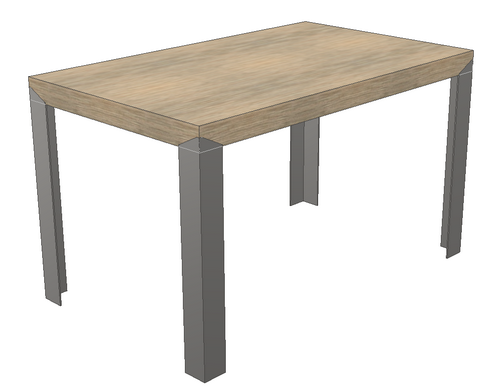
An example of the product “Actiu Table with Legs.iam”, where the “Leg of table.ipt” components require a special shaped recess in the corners of the desktop in order to attach the leg components to the desktop. The recess requires 2+3 axis processing.
This example requires a Front-End Macro “Recess processing for Leg.mpr”, which must be loaded into the Woodwop Macro library.
|
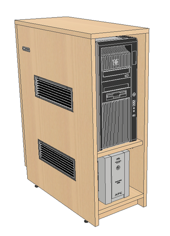
An example of the product “Computer box with equipment.iam” which uses some of the above components with Macros.
|