The Macro creation command is available in the part editing environment.
Running the command
Woodwork Design->Macro![]()

Dialog window for Macro creation
Macro List |
|
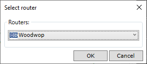
Creates a new JS Macro container. JS Macro is created for a specific processing device, so you need to select the device for which the given JS Macro will be created in the drop-down list.
Clicking "OK" creates a new line that displays the contents of the information container of the future JS Macro. As can be seen from the figure above, the processing of a component fixing hole can have many JS Macros. The order of these JS Macros in the list reflects the order of their generation in the final CNC program. This order can be changed by sliding the mouse over the entry to the desired position in the queue.
|
|
Name |
A custom JS Macro name, which can be changed by double-clicking the desired field. |
|
|
The user indicates whether the geometry cut out by the body of the given component in the part is exclusively processed by the given JS Macro and is invisible to the Woodwork for Inventor CAM system’s Auto-Technology Generator Solver. For example, we have a rectangular pocket where the steep corners are sculpted using a special Front-End Macro, but the pocket itself is removed by a standard pocket milling operation, which is recognised and automatically generated by the Woodwork for Inventor CAM’s Auto-Technology Generator. In this case, there is no need to indicate that the sculpted geometry is invisible to the generator. However, if the user has decided that the pocket sculpting is to be performed by another Front-End Macro, then a box must be checked so that the automatic generator ignores the cut geometry and does not automatically create the pocket sculpting operation.
|
|
Surface Body |
The user selects the component body with which the given JS Macro is associated. In order for the body to appear in the list, it is necessary that it has a “-” or “+” in front of its name.
|
|
Coordinate System |
Represents the coordinate system of the Macro base point. The Macro base point coordinate system can serve as the origin coordinate system of the given component, or it can be any user-defined coordinate system (User Coordinate System)
|
Main definition |
Coordinate System |
Selection of base point coordinate system for the given JS Macro. In the drop-down list you will see all the coordinate systems available for the given component and you have to select the one you want. By default, the coordinate system of the origin of the component is suggested.
|
|
Calling Porcedure |
Program edit window describing the JS Macro program.
|
Oposite Side Definition |
|
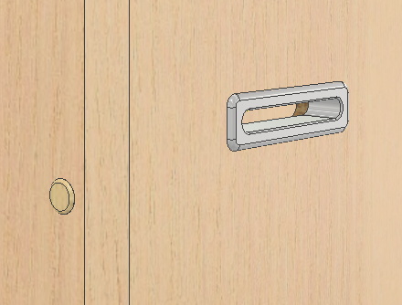
Reproduces the contents of the Main definition tab. In case the given Front-End program has to generate a hole through the part and can be processed on one side of the part or on the other side, an alternative processing procedure for the other side can be created for this JS Macro. As shown in the example below, the opening for a given component can be cut from either side. Analogy with a hole through the full thickness of the part. The hole can be drilled on either side of the component.
Alternatively, the reverse side JS Macro allows the generation of CAM technologies that do not require the generation of an additional program in the inverted state for the part just to obtain the required hole. To generate such a JS Macro, it is a necessary requirement that the opposite side JS Macro is bound to a coordinate system that is the opposite in its Z vector to the coordinate system that represents the main definition JS Macro. The drop-down list of coordinate systems automatically filters such potential coordinate systems based on the coordinate system defined in the Main definition of the JS Macro.
|
|
OK |
Automatically saves any last changes and closes the dialog.
|
|
Close |
Closes the dialog without saving any changes.
|
|
|
|
After a JS Macro or JS Macro Assembly is created for a component, the component is ready for use. When such a component is placed in the context of a furniture construction and the sculpt command is executed, JS Macro is automatically added to the part to be sculpted and it becomes visible to the Woodwork for Inventor CAM module. See the next section for how CAM operations are created on the basis of this transferred information.