There is a certain order to the development of Post-Processors.
The first step in developing a Post-Processor is to find an existing Post-Processor that best suits your needs and start by modifying its code. You will find the Post-Processors created by our team next to the Woodwork for Inventor data on your computer:
C:\Users\Public\Documents\Woodwork for Inventor\<Inventor version>\<Woodwork version>\SDK\Postprocessors
A brief description of the purpose and functions of these Post-Processors.
We will add to this list in the future.
|
When you find a Post-Processor that is close to, but does not fully meet the requirements of your CNC machine, you will have to modify it. The good news is that all Woodwork for Inventor CAM Post-Processors are open-source and JavaScript text files and can be modified without any restrictions using any text editor you are familiar with. There are various editors on the market that are optimised for working with software code, but we recommend Visual Studio Code. Using this editor offers many advantages for working with Woodwork for Inventor Post-Processors:
|
Post-Processor code is divided into several logical parts, some of which are mandatory (required). Typically, a Post-Processor consists of the following parts:
The first required part is dedicated to the general settings of the Post-Processor. It uses a “mandatorySettings” object whose fields must be specified.
export var mandatorySettings = { description: 'G-code Mach3', legal: 'Copyright (C) 2021-2022 by Celi APS, Inc.', longDescription: 'Generic G-code post based on Mach3', certificationLevel: 3, minimumRevision: 8, fileExtension: 'nc', setCodePage: 'ascii', unit: 'mm', operationSort: 'ByOrder', };
The other two parts of the code are used to define the formatting. The first one defines the formatting rules for the output information (CreateFormat), followed by the creation of the variables that use and manage those formats - (CreateModal, CreateVariable, CreateReferenceVariable, CreateIncrementalVariable). var nrStr = Utility.CreateFormat({ prefix: 'N', decimals: 0 }); var xyzStr = Utility.CreateFormat({ decimals: (mandatorySettings.unit == 'mm' ? 3 : 4), scale: mandatorySettings.unit, forceDecimal: true }); var nrIncVar = Utility.CreateIncrementalVariable({ first: 10, step: 10 }, nrStr); var xModal = Utility.CreateModal({ prefix: 'X' }, xyzStr);
The fourth part is for defining lateral transformations and is required. Here, the “sideTransforms” function is used to define how the coordinate system of each side is oriented.
 Side Coordinate System example
export function sideTransforms(sizes, corner, callFromNesting) { transforms.push(Spacial.CreateCoordinateSystem( 'Front', Spacial.CreatePoint(0.0, 0.0, -sizes.Thickness), Spacial.CreateVector(1.0, 0.0, 0.0), Spacial.CreateVector(0.0, 0.0, 1.0), Spacial.CreateVector(0.0, -1.0, 0.0))); …
The penultimate part contains the basic input procedure onPostprocess, which is also required. From here the Post-Processor starts its work and here you have access to the top data object – Job.
export function onPostprocess() { // Top accessible object -> Job for (var index = 0; index < Job.Clampings.Count; index++) { ... }
The last part describes the whole logic of the Post-Processor – how the Post-Processor produces the CNC machine format you need from the CAM data. This part of the Post-Processor is completely open, so you can write the code however you like.
|
First, you can find the Woodwork CAM Post-Processor API help file in the directory:
C:\Users\Public\Documents\Woodwork for Inventor\<Inventor version>\<Woodwork version>\SDK
The Post-Processor API has a number of assistive objects that facilitate the processing of CAM data. One of these objects is Spacial. It is used to create spatial objects such as Point, Vector, CoordinateSystem. These objects have methods that allow the execution of vector algebra operations that are often used in various processing of CAM data. For example, the following describes a coordinate system.
Spacial.CreateCoordinateSystem( 'Top', Spacial.CreatePoint(0.0, 0.0, 0.0), Spacial.CreateVector(1.0, 0.0, 0.0), Spacial.CreateVector(0.0, 1.0, 0.0), Spacial.CreateVector(0.0, 0.0, 1.0));
The second object - Utility, is used to create formatting methods and their variables. In addition, with the WriteFile procedure of this object you can write text data to a file.
Utility.WriteFile(fileName, fileExtension, additionalFolders, content, encoding, clampingName);
And the last object to mention is the ReferenceCoordinateSystem. This object has various methods to define a coordinate system oriented in any way. From the moment this coordinate system is declared in the program, the coordinates of all points or vectors are returned in terms of the last valid ReferenceCoordinateSystem.
ReferenceCoordinateSystem.SetToClamping(clampingName); … ReferenceCoordinateSystem.SetToSide(sideNormalVector); … var pointOnSide = point.ToReferenceCoordinateSystem();
|
One of the main advantages of the Visual Studio Code Editor is that it is extremely easy to debug code. A debugger is integrated into the Visual Studio Code environment to help speed up the Post-Processor editing and debugging cycle. It is an interactive debugger that works with both Woodwork for Inventor and Post-Processor. In other words, you can debug the Post-Processor code while working with Woodwork for Inventor and perform testing with real CAM data.
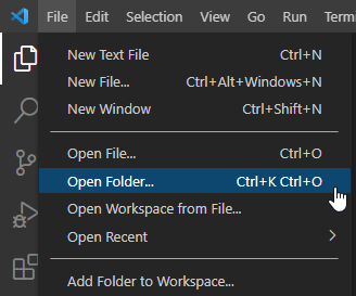
To start working with Post-Processor code, you should first open the working directory. By default, this will be the following directory:
C:\Users\Public\Documents\Woodwork for Inventor\<Inventor version>\<Woodwork version>\SDK\Postprocessors
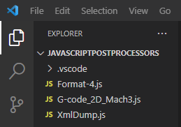
When you open the specified directory, you should see several files in the Code environment. Make sure you also see a directory called .vscode. This directory contains important information for connecting the debugger. Without this directory the debugging process will not work.
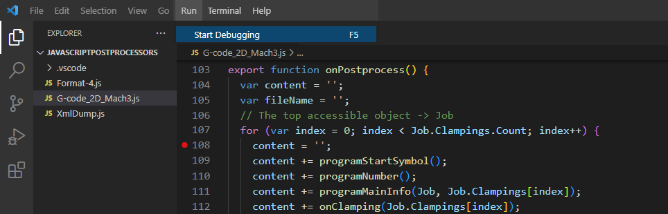
Selecting one of the JS files will open a specific Post-Processor. Place a brake-point anywhere in the code to stop the execution of the Post-Processor and start the debugging process by pressing the F5 key.
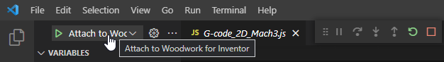
To make sure that the debugging process has started correctly, you should see a message about connecting to Woodwork for Inventor. In addition, additional debug buttons should appear.
You can now execute the Woodwork for Inventor CNC Output command, and the debugger will stop at the line of code where you have placed the brake-point. You can then execute a variable revision or step-by-step tracing of the program.
|