When describing the Front-End Macro generating program, it is important to understand the coordinate systems that can be used in the JS Macro program and how to manipulate the derived point and vector values that will be used to form the Front-End Macro body. A coordinate system is seen as a set of data that contains:
| ▪ | The origin of the coordinate system. |
| ▪ | Three unit vectors representing the orientation of the coordinate system in space: |
| ✓ | The X-axis normalised vector of the coordinate system |
| ✓ | The Y-axis normalised vector of the coordinate system |
| ✓ | The Z-axis normalised vector of the coordinate system |
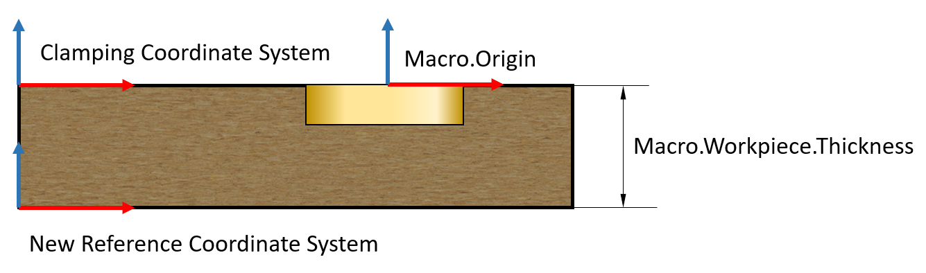
As mentioned above, the Macro coordinate system can be expressed in any other reference coordinate system. By default, this system is considered to be the Clamping Coordinate System of the workpiece. However, in the programming of the various Front-End programs, it is necessary to express coordinates in other coordinate systems. For example, the Front-End Macro call is executed in the coordinate system on the side of the part. Therefore, the JS Macro compiler has the possibility to designate a different reference coordinate system in any line of the JS Macro program, e.g. to make it equivalent to the Side coordinate system. And from this line onwards, all subsequent code that executes coordinate or vector returns will execute in the specified coordinate system.
For example, in the Front-End program, the coordinate reference in the Front-End Macro call procedure must be executed from the bottom of the part rather than the top of the part.
To do this, we can create a new reference coordinate system:
Macro.ReferenceCoordinateSystem.SetToClamping();
//Creates Shifting Vector for Reference Coordinate system. var ShiftVector = Spacial.CreateVector(0.0, 0.0, -Macro.Workpiece.Thickness);
//Shifts current Reference Coordinates System by Workpiece Thickness down Macro.ReferenceCoordinateSystem.SetNewOrigin(ShiftVector);
From this point on, all coordinate and vector queries will return values expressed in the new reference coordinate system.
If in the example given the workpiece thickness (Macro.Workpiece.Thickness) is 19mm, then
operator var Z=Macro.Origin.Point.Z, will return a value of 1.90cm.
Macro.ReferenceCoordinateSystem has a whole series of methods that allow you to define a coordinate system that is bound at virtually any point in space and oriented in any way in space.
|
Every operation in Woodwork for Inventor CAM is contained on a plane, which in Woodwork for Inventor terminology is called a “Side”. It is basically a coordinate system.
 Operation Side coordinate system
Many operations take place in a coordinate system which is the same as the Clamping Coordinate System. It is referred to as the Top coordinate system. However, by default, the Woodwork for Inventor module creates four more coordinate systems:
These can accommodate lateral operations. In panel processing, these are usually various lateral drilling operations. If required, freely arranged coordinate systems can be created based on the orientation of the JS Macro base point coordinate system: Custom Sides.
In the JS Macro programming system, access to the data of such a coordinate system can be implemented via the Macro.Side object. The base point and vectors of this object are returned in the current reference Coordinate System report.
In the JS Macro programming system, another variant of the Macro.Side object Macro.AlignedSide is provided. This object differs from the Macro.Side object only in that it returns the coordinate system in which the JS Macro operation is given, and its orientation is always the same as that of the Macro.Origin coordinate system. The starting points between Macro.AlignedSide.Origin.Point and Macro.Origin.Point may not be the same. The need to use such a coordinate system arises in cases where the Front-End Macro does not have a parameter defining the rotation angle of the Front-End Macro. It is then necessary to define a plane rotated according to the orientation of the JS Macro base point coordinate system and to generate the Front-End Macro call on it without the rotation angle argument. This is particularly useful if the Front-End Macro has a complex geometry and the angle argument complicates the whole description of the Front-End Macro.
Another use of Macro.Side.AlignedSide is that in a front-end CAM system, in order to describe oblique operations, you also have to describe oblique coordinate systems. For example, in the Woodwop system such a coordinate system is represented by a Level entity. To define it, you need to specify a starting point and three rotation angles: around the Z-axis, around the X-axis and around the oblique Z-axis. With the Macro.Side data, calculations can be carried out to find these three angles and used to define the Level entity of the Woodwop system. Once such a calculation function has been created, it can be exported to a separate JavaScript library and used to define the necessary coordinate systems in the Front-End Macro call procedure. You can find an example of such a JS Macro if you open the Woodwork for Inventor Macro examples and look at the Macro description for the component “Clamex-P-14 groove Without Drill.ipt”. Here you will find a function that is derived in a separate Utils library, Utils.calWoodwopPlaneAngles, which uses the Macro.AlignedSide orientation vectors to calculate the required angles for the Level entity definition. These angles are returned as an array of three numbers.
Other Front-End CAM systems may require a different conversion function. For example, in the front system tpaCAD, three points and the origin of the coordinate system are used to define the oblique coordinate system. Thus, when writing a JS Macro output program for such a system, a different data processing is required to generate the data for the oblique coordinate system in which the given Front-End Macro operation is contained.
|
Each JS Macro has an associated reference point or Macro Base Point Coordinate System. The description of this coordinate system is carried by the Macro object and its data container Origin:
Macro.Origin.Point – the origin of the Macro Base Point Coordinate System. wPoint type variable. Macro.Origin.XAxis – the orientation vector of the X-axis of the Macro Base Point Coordinate System. wVector type variable. Macro.Origin.YAxis – the orientation vector of the Y-axis of the Macro Base Point Coordinate System. wVector type variable. Macro.Origin.ZAxis – the orientation vector of the Z-axis of the Macro Base Point Coordinate System. wVector type variable.
When a furniture component is inserted into an assembly and a Sculpt operation is performed, the JS Macro program assigned to the component’s Sculpt body is automatically transferred to the part. At the same time, the Macro Base Point Coordinate System information is transferred.
The positioning of the part is determined during the CAM technology development. The entire CNC program is built according to the Clamping Coordinate System. The Side Planes of the workpiece are built in relation to it, which basically represent the coordinate system. If the technology requires oblique processing, then freely spatially oriented planes (Custom Planes) are built. As you know, all operations in Woodwork for Inventor are assigned to a plane (side) of the part, and all points in the trajectories of the operations are expressed with respect to the plane to which the operation is assigned. The Macro processing operation is no exception. When compiling a JavaScript program, it is important that the JS Macro programmer is able to manipulate the Macro base point data in any coordinate system.
By default, the base point coordinate system parameters are returned in the Top plane coordinate system, which coincides with the Clamping Coordinate System of the part. Depending on the operations performed by Macro, the Macro base point coordinate system may need to be expressed in either the workpiece plane or in a custom coordinate system. In order to free the programmer from the complex transformation of coordinate system data, the system provides the following mode of operation:
|

