Autodesk Inventor uses a unified Autodesk material and appearance database, which is used for the entire Autodesk component group. In its database, Woodwork for Inventor add-on uses items from the aforesaid database, complementing this information with data necessary to ensure functioning of Woodwork for Inventor. Such a synchronized coexistence of the two databases requires attention and its management is rather complicated. The actual design process faces intense change of material nomenclature; therefore, it is difficult to create and maintain new synchronized items in Woodwork for Inventor and Autodesk Inventor databases. For this reason, in the construction process with Woodwork for Inventor, materials are assigned in two stages:
| 1. | A general Woodwork for Inventor material (also known as material group) is assigned to parts. This assignment defines the type of material. For example, board, profile banding, desktop, etc. The material also defines the function of the part to which the material is assigned. For example, facade part of the first colour, facade part of the second colour, body, etc. |
| 2. | At the last stage of construction, the general material code, name and appearance can be replaced with the specific material code, name and appearance. |
When performing the replacement command, Woodwork for Inventor generates a material summary for the model. Materials in the summary are presented based on the Woodwork for Inventor material concept. Here, they are grouped into regular materials and materials that have colours.
Regular materials include:
Description of such materials includes the following:
Materials that have colours include:
Description of such materials includes the following:
 Example of a material that has colour. In this case, explanation of appearances of a laminated board
The materials are additionally grouped according to geometric parameters. Examples include board thickness, edge band width and thickness, profile cross-section dimensions, etc. Geometric parameters that define the material depend on the material type. Below is a table showing material types and the corresponding parameters:
If the material used for the part has the same code, name, appearance, colour, colour code, colour appearance (if the material has colour) and geometric parameters, then it is the same material.
 Display of material summary window
The example above shows how Woodwork for Inventor analyses the model and materials used for the model parts. It presents these materials in the summary grouped by material type and material size.
|
A material can be replaced in one of the three ways:
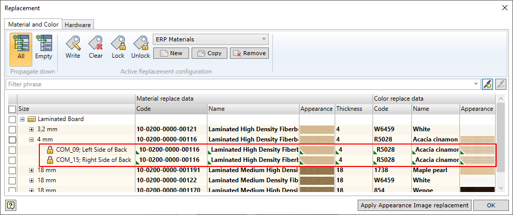
The replacement desktop always shows the replaced values of the material. If the user wants to see original values, hover over the cell to display the Tool tip, which shows the original values saved in the Woodwork for Inventor material database. The fact that the cell value has been changed is indicated by bold font of the cell content. Such changed information will be used at all information export points, where the material is mentioned. This information is used by BOM Generator, Auto Plot and CNC Output.
 Material summary window after material replacement
|
As mentioned above, the user can change material codes, names and appearance. In other words, virtually replace a general material group with a specific material. Such replacements can often be applied to other pieces of furniture being designed. All such replacements can be saved as replacement configuration. When constructing another piece of furniture, you will simply have to apply this configuration. Having found the material mentioned in the replacement in the material summary for the model, Woodwork for Inventor add-on will automatically make the replacement. This way the user can memorise the most popular and tested material or colour replacements and apply them in one go without separately changing data for each general material. The user can create as many configurations as he wants. The user can also remove such configurations. Only Default configuration installed with Woodwork for Inventor cannot be removed. Using these configurations and the same geometry of the piece of furniture, the user can quickly produce information necessary to begin the production with different materials.
The most recent replacement configuration opened for editing will be treated as the active replacement configuration. It can be opened from the configuration tool bar. Please note that data of the active replacement configuration will be used in all processes of Woodwork for Inventor. Data of the active replacement configuration are used for the following commands:
|
The user can keep material and colour lists in MS Excel files. Values from this file can be copied to the replacement cell. Woodwork for Inventor has a mechanism for linking the data of a MS Excel file to the Interface and presenting them in a convenient way. The picture below provides an example of how MS Excel worksheet columns can be linked with the application data fields.
 Example of linking with MS Excel worksheet
As mentioned above, replacement data are provided in a simple MS Excel worksheet in freely arranged columns. One worksheet can be linked to all material types or each material type can be linked to a separate data worksheet. Data can be linked to a material and/or colour. Linking to a material or colour depends on the location, from where the replacement dialogue box is opened.
The replacement worksheet and linking dialogue box are opened by clicking on the symbol
Attention! It should be kept in mind that linking for colours is done when the link dialogue box is opened via Colour replace data (see figure below). To create the link for materials, the dialogue box should be opened via Material replace data. The user can understand what the replacement data are linked to from the header of the dialogue box and from what is displayed in the linking window. Only the materials that have colour can be used for linking to colour.
 Opening colour replacement window
Entering additional data for the material or colour. When setting up the link, three fields are always given:
If the user needs more fields, he can add a new field and link it to the field in MS Excel worksheet. In the example above, you can see how Producer field is added. This way, you can specify additional material characteristics such as fire safety of the material, material names in additional languages, etc. Values of these fields can be opened in specifications and drawings by means of keywords.
Synchronous linking of material and colour. In certain cases, it is necessary to link a colour to a different material from the specification. This usually happens when using ERP systems. In the example below you can see how colour generates a different material code every time.
If you want the colour selection result in change to the material code or vice versa, you have to link the material and the colour to the same worksheet. In this case, selecting a colour will result in the appropriate change in the material cell and vice versa.
Registering appearance images. The user can change not only the digital information, but also the appearance of the material or colour. To do this, MS Excel file has to contain a data column specifying the path to the image file that will be used to change the appearance. Image files have to be located in the same catalogue as MS Excel file or they can be stored in subdirectory located on the same path as the MS Excel file.
Instructions on how to create a configuration, set it up and use it are provided in the video below.

|
Material replacements are stored in configurations. However, in some cases it may be convenient to store them directly in the part component. For example, we have a smart iBox drawer. In order to avoid thinking which materials should be used to produce the drawer every time, the material replacement can be configured once and saved and locked in a component. In such case, an iBox element inserted into a new assembly will not require a respective replacement configuration, because each component will know which replacement material has been assigned to it.
Another case is configuring an individual material replacement for each item and therefore, an individual replacement configuration has to be created. This way, configurations accumulate in the system, which makes it difficult to sort them out over time. Using the save and lock feature allows the user to save the material replacement results directly in the parts and not to store the respective replacement configuration. Every time such item is opened, its parts carry their own material replacement values.
The example below shows several components that have had a replaced material saved and locked. Used in any other item, these parts will know which material is used to produce them. Of course, the user can unlock such part at any time and change the replacement material or clear the entry altogether, thus making the part sensitive to replacement configuration settings again. For more information about these processes, click here.
|
Only code and name appear in purchased components. Similar to the case of materials, here the user can change the code and the name. This way the same confirmat screw in the assembly model can be ordered using different codes from different suppliers.
Changes to the purchased components can be made only in the BOM generator dialogue box. Click here to see a detailed description of how the Woodwork for Inventor replacement command works.
|
After performing replacements of field values, modified field values will be exported to BOM specifications via the keywords. For example, Item.FillWorkpiece.Material.colour.Code keyword exports a modified workpiece colour (if any). However, there may be cases when you have to indicate, in the BOM specification, the field values that were obtained during the reading of the CAD model by the Woodwork for Inventor BOM generator. In other words, original field values are required. In this case for each item that defines the material and has a replacement value, there is an option of extracting an original value obtained during the reading of the model. In this case, you can use the Original prefix for each such modified field.
For example, we need to know what an original colour code of a given material is. For this purpose, you need to enter the Material.Original.colour.Code keyword in the table description. Or, assuming that a material name is required: Material.Original.colour.Name.
In case a replacement was not performed, the original name matches the replaced name.
|