The output information from the Woodwork for Inventor add-on is a text file which can be read by a given machine. Traditionally, machines are controlled by a specific language which is generally widely known as G-code. It is a low-level language describing tool movements and other additional technological data such as: tool feed rate, spindle rotation speed, starting and stopping rotation, etc. In other words, this language can be compared to low-level computer programming. This language has numerous dialects which occurred due to the variety of CNC machines, the need to describe different processing tools and to reflect the technological processing capabilities offered by the CNC machine (see figure below).

Different tool arrangement in different machines
When creating CNC programs, if problem arises with the G-code language in that the programmer must have a very good knowledge of the technological capabilities of the CNC machine and of the language dialect itself required to create a CNC program. Multiple rather complex geometric calculations have to be performed when converting the drawing information into the format suitable for a CNC program. It is particularly relevant when describing contour processing. Another problem lies in the fact that the program is checked only when it starts running on the machine.
With the advance of computers and software, manufacturers of machinery were trying to find ways to facilitate, accelerate and standardize the CNC program creation for their machines. This resulted in the emergence of software known as front-end CAM systems. These are higher-level software systems which provide a programming environment which facilitates and accelerates the creation of CNC programs. These programs usually have a developed graphic environment which offers a clear visual representation of an operation being performed in the part itself. Moreover, these systems standardize the CNC programming task to the maximum extent possible for different equipment of a given company, i.e. a uniform program interface required for program creation is provided for all types of machinery.
Basically, these programs also generate the G-code. Here the specifics of each machine are realized through the operation of special program Post Processors and also through the writing of machine configuration. These systems usually have two versions:
| ▪ | One is a Desktop version. |
| ▪ | The other is a version that works in the machine control console. |
They are virtually the same in terms of their interface. What is really convenient is that a technologist-programmer and a machine operator can see the same program visualization in the both versions. Today woodworking machines have virtually no capability to be directly programmed using G-code. The interpretation of the G-code is well-hidden and programmers perform the entire programming only through these front-end CAM systems. The following are some of the typical front-end systems:
| 1. | Homag group: Woodwop |
| 2. | IMA group: IMAWOP |
| 3. | Biesse group: Biesse works or B-solids |
| 4. | Format 4 group: TPA CAD |
etc.
In the Woodwork for Inventor CAM module, information is outputted in the form of G-code only in exceptional cases. A Post Processor is always written for a front-end CAM system. Such a method allows re-checking the generated program in the front-end CAM system and performing last-minute processing corrections, if such are necessary, in a convenient and simple manner. Moreover, this allows using the same Post Processor for different machines.
Further in the text the term “CNC machine” refers not only to a specific CNC machine but also to a configuration which services the data out to front-end systems or even to any graphic system, e. g. AutoCAD.
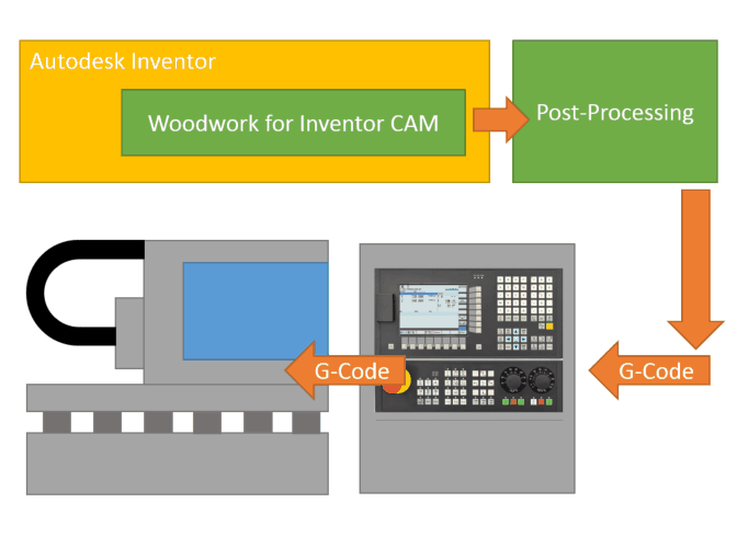
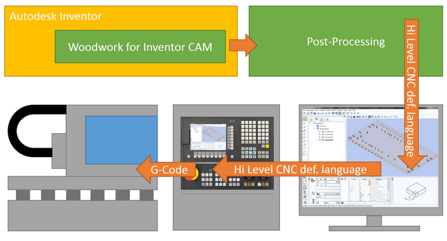
Thus we can distinguish the following two Woodwork for Inventor CAM operation schemes:

The operation scheme with direct output to G-code

The operation scheme which includes data output to a high-level language describing a CNC program
A special program/interpreter (Post Processor) is written for each machine or each front-end CAM system which converts the Woodwork CAM information to a specific output form which is understandable by a given machine or a CAM system.
As you can see in the figure above, machines may have different design arrangements and may use different tools to realize the functionality intended for the CNC machine. Moreover, these machines may have different tool setups, depending on the type of manufacturing used. When creating a CNC program, these differences and existing limitations should be taken into consideration. For this purpose, there is an option to define the machine’s configurations and to use this data in different Woodwork for Inventor CAM work stages. Let us now look at what kind of machine data is described in these configurations.
Configuration data about CNC machines
The configuration data of the CNC machine is hierarchically dependent in the following descending order:

| 1. | The highest level is the CNC machine containing specification about the machine itself, the spindles operating in it as well as the tools mounted in the spindles. |
| 2. | The next level is the spindle which realizes the movement of the tool within the machine. |
| 3. | The lowest level are the tools themselves. |
The sections below discuss the information stored at each of the above levels: