Setting CAM technology parameters for a material group

Top | Previous | Next


Woodwork for Inventor material database allows specifying the settings required by CAM Solver for fill material. This option is opened once the user places the cursor on the material thickness branch on the left side of the material editor window. Such settings are possible for fill materials only. CAM technology settings cannot be specified for cover materials.


Please note, that not all fill materials have the shape nesting CAM technology settings section available. These settings can be specified only for the following material types:


1.Board
2.Laminated Board
3.Multilayer Board


Material Editor CAM settings for Material


hmtoggle_plus1Thickness boundary


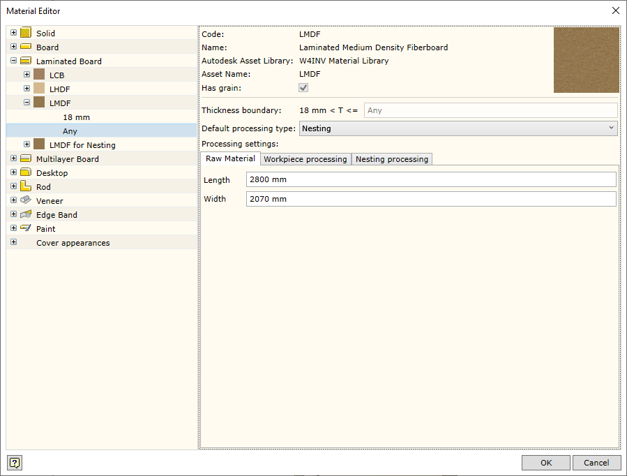
Displays the material thickness range, for which CAM processing settings are created..


hmtoggle_plus1Default processing type


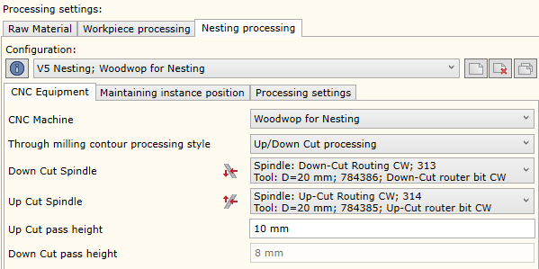
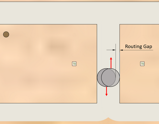
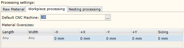
Setting the processing type, which is taken into account by CAM Solver when automatically generating CAM technologies, unless the user specifies otherwise.

Two options are available:


1.Nesting: creating CAM technology for shape nesting.
2.Workcentre: creating CAM technology for workcentre.


hmtoggle_plus1Raw material


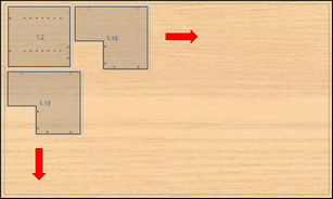
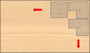
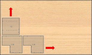
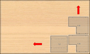
Specifying the measurements of raw material sheet. Generally, these measurements are used for creating preliminary layout of parts on raw material sheets in the nesting program.


hmtoggle_plus1Work Center processing


Material Editor Workcenter processing settings


Default CNC Machine

CNC workcentre for which CAM technology will be generated may be specified. Several workcentres may be specified. This means that after all processing in the first workcentre is completed, the next workcentre will continue with the remaining processing operations.


Material Oversizes

The user can specify the oversize for a material, which will be automatically used for the workpiece. This affects the operation of CAM Solver in determining the CNC base point and in making decisions, which operations have to be performed in processing the part. The oversize may be applied according to the workpiece size. For this purpose, the user may specify required length and width ranges in the table and assign the required oversize accordingly. Later on, during the construction phase, the oversize may be adjusted.


hmtoggle_plus1 Nesting processing


Material Editor Nesting processing settings


The user can create configurations of shape nesting technological settings, specifying the following:


1.CNC equipment: CNC machine and nesting contour processing spindle(s).
2.Maintaining instance position: methods and settings of keeping the part on the worktable during shape nesting.
3.Processing settings: shape nesting contour mill operation settings for the selected CNC machine.


Configuration info

Displays the materials for which the given configuration was applied.

New Configuration

Creating a new configuration.

Configuration delete

Deleting configuration.

Copy configuration

Copy of configuration.


This way, the user can create one configuration of shape nesting settings and apply it for selected materials. The configuration does not depend on the material. On the other hand, each CNC machine can have several configurations which provide the settings for shape nesting routing. This can be used when creating a shape nesting technology manually.


As shown in the figure above, the bottom tabs show the settings of the current configuration. When the user opens the shape nesting technology settings, they are displayed in grey colour. It is an additional warning than changing configuration settings will cause changes for all materials for which this configuration was assigned. The user can click anywhere in the grey area to show normal dialogue colour and continue work.


CNC machine


Allows selecting any CNC machine that exists in the Woodwork for Inventor database..

Through milling contour processing style

Allows specifying how the nesting shape contour should be processed. There are three available options:

One Spindle processing - nesting contour milling with one spindle using a conventional mill
Up/Down Cut processing - nesting contour milling with two spindles loaded with different mills by two routes. During the first route, the contour is milled and the chip is pressed downwards, while during the second route it is pressed upwards. This helps to achieve higher cutting performance. Both mills must be of the same diameter.
Compress Spindle processing - nesting contour is milled using a special tool which compresses the chip towards the centre.


All these options require different settings.


One spindle processing


Nesting Single spindle Single Spindle


Specifying the spindle on the selected machine for shape nesting contour milling.


Up/Down Cut processing


Down Cut Spindle Down Cut Spindle


Specifying the spindle with a tool which mills the nesting contour while pressing the chip downwards..

Up Cut spindle Up  Cut Spindle


Specifying the spindle with a tool which mills the nesting contour while pressing the chip upwards.

Up Cut Pass Height

Specifying the milling height, at which the movement is changed from down cut to up cut spindle.


Compress spindle processing


Compress spindle Compress Spindle


Specifying the spindle loaded with a compress mill.

Up Cut part length

The length of the part pressing the chip upwards. This is important in setting the minimum depth of the first route in layer-by-layer contour milling operations.


In shape milling operations, the option of partial cutting of the part contour in a raw material sheet is often helpful in order to prevent accidental shifting of the part while processing the adjacent parts. This helps to avoid damaging the whole sheet during processing. For this purpose, connections are made between the cut part and the whole sheet. There are two ways to do this:padaroma:

1.Leaving small bridges;
2.Leaving a thin unmilled layer around the whole contour perimeter, also known as onion skin.


Position Mainatining Type:


None


No maintaining of position.

by Bridge


Maintaining position using bridges.

by Onion

Maintaining position using onion skin.


by Bridge


Max piece area to apply bridges

Bridges can be used only for parts with the area smaller than indicated. The option “Any” means that bridges maintaining the position will be used for all parts.


Bridge Width


Bridge width that is being left

Bridge Height


Bridge height that is being left

Bridge if margins is bigger than


Bridges are used for parts that are on the edge of the raw material sheet (note: sheet margins must remain intact).

Merge neighboring Instance bridges if distance is less than


If bridges are made between adjacent piece instances and the distance between them is smaller than indicated, the bridges are merged.

Minimum amount of bridges for Piece Instance

Minimum number of bridges automatically made per piece instance in a sheet..


By Onion Skin


Max piece area to apply Onion Skin


Onion skin can be used only for parts with the area smaller than indicated. The option “Any” means that onion skin maintaining the position will be used for all parts.

Skin Thickness

Onion skin thickness that is being left.


This tab is used to specify mill operation settings for nesting shape contour..


Milling type


Sets the side of processing of the nesting shape contour. More information about this option is available here.

Tool trajectory correction type


Tool trajectory may be provided to the machine as specifying the central position of the tool (software) or contour of the part (hardware) and the machine converts it to central coordinates. More information is available here.

Milling allowance


Specifies the oversize in shape nesting milling operations. Please note that when generating a milling trajectory for shape nesting contour, pre-mill allowance specified in system settings is also taken into account.

Depth allowance


Specifies the oversize depth in milling operations..

Corner Recess On/Off


Enables/disables automatic tool approach to the material in recesses at the corners of the shape nesting contour.

Stepover


Sets layer-by-layer approach step in shape nesting milling operations.

Lead In ir Lead Out

Sets the method of the milling tool approach to/withdrawal from the material and its distance.

Available options:


Direct - direct approach or withdrawal.

Ramp - ramp approach or withdrawal. Ramp size must be additionally indicated


Routing Gap

Defining the thickness of material, which must be left for milling of the adjacent part after the milling of the current part is completed.


Nesting Routing Gap


Piece Instance placing corner

Sets the corner from which the arrangement of piece instances has to be started. Available options::


Left Back


Right Back

Nesting placing Left Back


Nesting Placing Right Back


Left Front


Right Front

Nesting Place Left Front


Nesting Place Right Front


Sheet clamping corner

Defines which corner of raw material sheet is the base point in the final CNC program. Available options:


Left back clamping  corner icon

Left Back


Right Back clamping  corner icon

Right Back


Left Front clamping  corner icon

Left Front


Right Front clamping  corner icon

Right Front


Nesting Margins

Sets the distance from the edge of raw material sheet to the piece instance to be cut..