Definition of furniture hardware elements
In Woodwork for Inventor, a furniture hardware element is a component that, when placed in the furniture model, brings together with it required changes in the forms of the parts being joined, ensuring a desired assembly of parts. If needed, this hardware element can additionally bring a component estimated in BOM specification which implements such joining. As shown in the figure below, this may include making several holes in a material (e. g. minifix with a dowel) or subtracting and attaching elements in a material (e. g. joints used in woodworkers products).
Furniture hardware can be created as Autodesk Inventor:
1. Part
2. iPart
3. Assembly
4. iAssembly

Parts joining examples
Description of structure holes and tenons
Subtraction or attachment body is expressed as Autodesk Inventor part body which name starts with the symbol "+" or "-".
"+" - means that the body will be joined to the body of the furniture part intersecting it.
"-" - means that the body will be subtracted from the body of the furniture part intersecting it.
"@" - means that the body is neutral and it does not participate either as a form modifying body or body which form is modified by another body.
"#" - calculated body. Woodwork for Inventor considers that only one body in the part model reflects the part form. Meanwhile, other bodies perform auxiliary function. By default, such body is the first body which is contained in the part body list and does not have a prefix "+" or "-". If the user considers that such a body is not the first in the list, then this body may be marked with the "#" symbol.
It is important to note that Woodwork for Inventor performs a Sculpt operation faster provided that only subtraction bodies participate in the construction.

Mortise and Tenon joint
In the above figure, you can see a woodworking joint consisting of a Tenon & Mortise joint in the wooden furniture parts. As you can see in the part reflecting this joint (enclosed in red rectangle) we have two bodies: + Tenon and - Mortise. These bodies are respectively subtracted and attached to intersecting parts. Woodwork for Inventor attachment and subtraction operations can be performed in the following order:
1. Executes body subtraction.
2. Executes body attachment to the intersecting bodies.
Subtraction or attachment bodies can be included in the part or assembly level. Irrespective of this, Woodwork for Inventor will perform the above-mentioned sequence of actions and will execute required part form modifications needed to create a joint between the parts. A joint can be created just by using a part form modification. Such joints are widely used by woodworkers. Examples include the aforementioned tendon and mortise joint or dovetailing the sides of the drawer.
On the other hand, a confirmat joint carries with it not only holes in parts but also a confirmat itself which has to be mentioned in the specification as a purchased product. There are two available options for including such a component:
1. An assembly is created containing a hardware component itself and a part representing a subtraction body.
2. A hardware component model is created containing a hardware component body and a hole body designed alongside it.
A component body that starts with the symbol "+" or "-" is considered to be a body representing a hardware component. The property tab data filled for such a component is transferred to the Woodwork for Inventor BOM generator and is exported into a BOM specification. Below is presented a standard confirmat component with a hole in which two bodies (Part Body) and (-Hole Body) are created. One of them reflects the body of the component itself, whereas the other (with the minus sign) represents the body of the hole being cut.

Confirmat with a hole
Indirect Component Definition
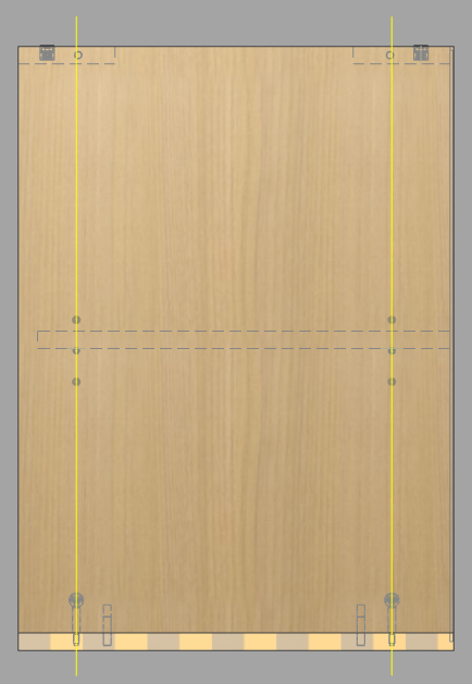
Woodwork for Inventor supports another method of defining an assembly (Indirect Component Definition). For example, it is convenient to create a part in which four attachment components placed in the four corners of the board are displayed. Using parameter settings, the user may enter information about these components in this part, and in the product BOM this part will be shown as an assembly of four components and not as a single part.
Indirect component definition in iLogic component
The figure above shows a designed part which represents a board joint in four corners. It can be flexible and adapt to the furniture form. If we will include the variables named as follows in the part parameters:
| ▪ | CompName(n) - component name |
| ▪ | CompCode(n) - component code |
| ▪ | CompQuantity(n) - component quantity |
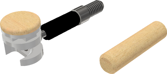
Where (n) means a number indicating a component order number. The way the Woodwork for Inventor add-on considers such a combination of these three parameters with the same component order number is that a part with such parameters inside it is treated as an assembly. During BOM generation, these parameters are interpreted as BOM items, and, in terms of Woodwork for Inventor, are fully calculated components. For example, you can see from the figure below that the Woodwork for Inventor add-on will show such a part in a specification as an assembly consisting of two parts: Minifix CAM - MF D15 4 units and Dowel - D8 6 units.

Components expressed as a parameter records
It is easy to apply iLogic options to such a part and allow the user to configure such a joint. The above-mentioned configuration is performed by disabling/enabling the insertion of the central dowel in the joint or by disabling/enabling eccentric caps.
Indirect component definition in iPart component
Another way to indirectly define components is to specify their Part Numbers, Descriptions and Quantity in iPart component table.
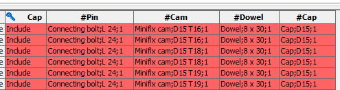
In this case, it is sufficient to enter a column preceded by # for each component in iPart component table. The column name should be such that it makes it easy to understand which component the information is about. The content of the rows in such a column has to be given in the following order:
<Description>;<Part Number>;Quantity
Data fields are separated by ";".
Hardware arrangement
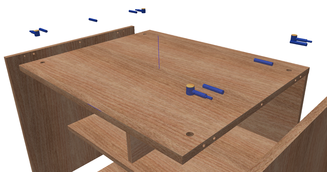
If you look at the furniture structure, you can state that hardware elements in it are arranged based on its faces and assembly axes. The figure below shows that axes define the position of the furniture hardware in the furniture model: in this case the position of the Minifix cam and shelf bracket.
The user can easily create such axes in the furniture model as Autodesk Inventor Work Planes.
Woodwork for Inventor has its own component arrangement method which uses iMate constraints which are pre-written in hardware elements. This command, in is essence, is a modification of the Autodesk Inventor command (Place Constrain). The constructor simply needs to indicate to which reference geometric elements a specified component has to be attached, and, taking into account the specified reference geometric elements, it automatically multiplies in all possible position combinations. For example, for the Confirmat type connection, it is enough to indicate: (1) a plane into which the screw will be inserted; (2) side planes based on which the screw will be positioned in a side direction; (3) axis planes. The screw is multiplied and arranged in proper positions in the furniture model.