Accessed via the menu: Components output to drawing -> Part -> Holes -> Hole dimensioning
This sub-menu item is used to order automatic output of hole dimensions to a drawing. It is also used to configure dimensioning parameters.
The dimensioning configuration window has two tabs:
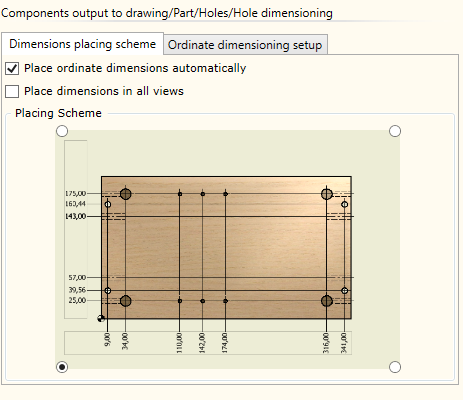
| ▪ | Place ordinate dimensioning automatically: orders automatic output of dimensions to a drawing. |
| ▪ | Place dimensions in all views: defines dimensioning in cases where more than one part view is ordered and hole dimensions are placed in several views. The view in which dimensions will be placed is selected depending on the hole orientation in the view. The view with the back of the hole facing the viewer has the priority. |
| ▪ | Placing Scheme: the panel is used to select the dimension placing scheme. |
|
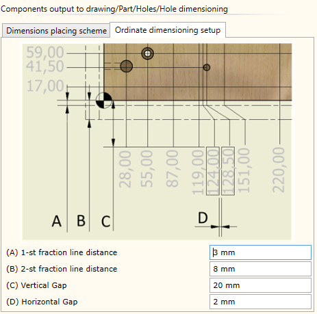
Hole dimensions are placed as ordinate dimensions. Here, you can configure parameters that control the form of these dimensions.
|